Display apparatus

a technology for display apparatuses and displays, applied in the field of display apparatuses, can solve the problems of difficult effective cooling, low heat radiation efficiency of display apparatuses, disadvantages of mounting display apparatuses on walls, etc., to prevent the temperature from rising of display apparatuses, improve the reliability of display apparatuses, and reduce power consumption

Active Publication Date: 2011-12-27
MAXELL HLDG LTD
View PDF5 Cites 2 Cited by
  • Summary
  • Abstract
  • Description
  • Claims
  • Application Information

AI Technical Summary

Benefits of technology

[0007]Enlarging the screen of a display apparatus (also denoted as a TV set or simply as a set) increases the power dissipation and heat generation of the display unit (panel unit). Meanwhile, making thinner the display apparatus lowers the heat radiation efficiency. This is because the display apparatus contains not only the display unit but also such heat generating components as transformers and driver ICs which are difficult to reduce in size. Although these heat generating components are cooled by air circulation within the display apparatus, thinning the display apparatus makes it necessary for them to be arranged with less space. Since air circulation paths are blocked, effective cooling is difficult.
[0010]It is an object of the present invention to suppress the temperature rise of a display apparatus mounted on a wall and consequently improve the reliability of the display apparatus.
[0013]According to the present invention, it is possible to improve the reliability of a display apparatus by preventing its temperature from rising higher than tolerated regardless of how the display apparatus is installed. In addition, according to the present invention, it is possible to reduce the power consumption when the display apparatus is mounted on a wall.

Problems solved by technology

Meanwhile, making thinner the display apparatus lowers the heat radiation efficiency.
This is because the display apparatus contains not only the display unit but also such heat generating components as transformers and driver ICs which are difficult to reduce in size.
Since air circulation paths are blocked, effective cooling is difficult.
Further, mounting the display apparatus on a wall is a disadvantage in the external cooling of the TV set since just a small space of, for example, about 2 cm, is left between the rear of the TV set and the wall while a space of about 10 to 15 cm at least is left therebetween if placed on a stand.
Thus, in the wall-mounted state, cooling of the display apparatus by convection at the rear thereof may be so insufficient as to raise the internal temperature of the set higher than tolerated.
This may deteriorate the performance and reliability of the set.

Method used


Image

  • Display apparatus
  • Display apparatus
  • Display apparatus

Examples


Embodiment Construction

[0020]Based on the drawings, the embodiment of the present invention will be described below.

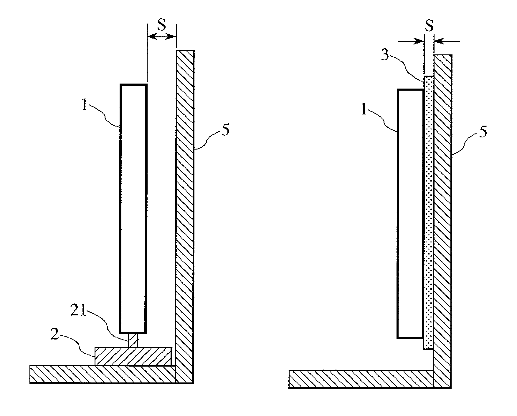
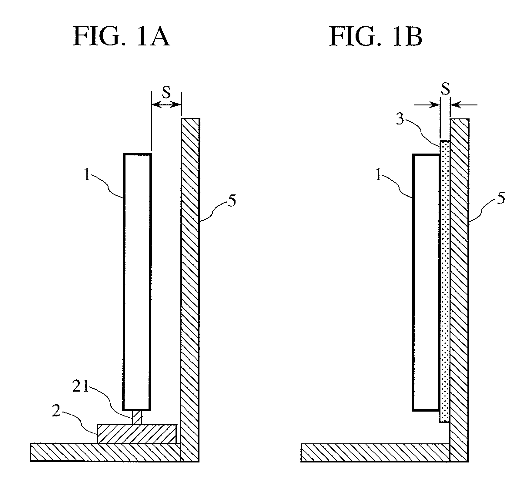
[0021]FIGS. 1A and 1B illustrate two ways of installing a display apparatus of the present invention.

[0022]FIG. 1A illustrates a first way of installation or floor placing. Into the bottom of the display apparatus (set) 1, a support member 21 of a TV stand 2 is inserted so that the TV stand 2 supports the set 1 from below. In this case, if the stand 2 has a width of about 30 cm, a space of at least 10 to 15 cm is kept between the rear of the set 1 and a wall 5.

[0023]FIG. 1B illustrates a second way of installation or wall mounting. The set 1 is fixed to the wall 5 with wall mounting member 3. In this case, a space S of, for example, about 2 cm is kept between the rear of the set 1 and the wall 5. The space S between the set 1 and the wall 5 constitutes the heat radiation space of the set 1. If the set 1 is mounted on a wall as shown in FIG. 1B, this heat radiation space is very narrow, lower...


PUM


Abstract

The present invention improves the reliability of a display apparatus by suppressing the temperature rise of the display apparatus mounted on a wall. The display apparatus is provided with a wall mount switch to detect a wall mount member if the wall mount member is attached to the rear of the display apparatus. If it is detected by the wall mount switch that the display apparatus is mounted on a wall, the display power supplied to a display unit is set lower than normal by a power controller. This suppresses the temperature rise of the apparatus mounted on a wall.

Description

CLAIM OF PRIORITY[0001]The present application claims priority from Japanese patent application serial No. JP 2008-219283, filed on Aug. 28, 2008, the content of which is hereby incorporated by reference into this application.BACKGROUND OF THE INVENTION[0002]1. Field of the Invention[0003]The present invention relates to a display apparatus which display images by using plasma display panels (PDPs), liquid crystal displays (LCDs) and the like and, in particular, to a display apparatus which suitably suppresses the temperature rise thereof if mounted on a wall.[0004]2. Description of the Related Art[0005]In response to digital high definition television broadcasts, recent television receivers have advanced toward higher quality and larger screen ones by using such thin display devices as PDPs and LCDs. Also in terms of installation for practical use, wall-mounted TV sets have appeared in addition to those supported by television stands which are set on floors. For use in the wall-mou...

Claims


Application Information

Patent Timeline
Patent Type & Authority Patents(United States)
IPC IPC(8): G09G5/00G09F9/00G09G3/20G09G3/296G09G3/34G09G3/36H04N5/66
CPCG09G5/00G09G2320/041G09G2330/021
Inventor KUBOTA, HIDENAONISHINAKA, YUZOYAMADA, YUTAKA
Owner MAXELL HLDG LTD
Why Eureka
Try Eureka