Suspension height adjustment mechanism

a technology of suspension height adjustment and suspension spring, which is applied in the direction of resilient suspension, vehicle spring, transportation items, etc., can solve the problems of reducing the adjustment time and physical effort involved in adjusting the suspension

Inactive Publication Date: 2012-01-03
MCINTIRE KEVIN JOSEPH
View PDF2 Cites 89 Cited by
  • Summary
  • Abstract
  • Description
  • Claims
  • Application Information

AI Technical Summary

Benefits of technology

[0020]such that, in use, rotation of the tool engagement portion causes the spring support to axially translate along the rotatable assembly, thus adjusting the height of the suspension.
[0021]Advantageously, embodiments of the adjustment mechanism provide a simplified adjustment arrangement. The adjustment mechanism can be easily used since adjustment is achieved merely by turning of the tool engagement portion. Advantageously, the tool engagement portion can be easily adjusted by a fast ratchet wrench adjustment, air impact wrench, 24 volt impact wrench, standard or compact ratchet wrench, electric or pneumatic powered nut running tools or by an active suspension system having its own motorized driving unit. This considerably reduces the adjustment time and physical effort involved in adjusting the suspension.
[0022]A second advantage of embodiments of the adjustment mechanism is that, in most situations, because of the more direct access, the suspension system does not need to be jacked up and the wheels removed before adjustment can take place.
[0023]A third advantage of embodiments of the adjustment mechanism is that use of a special ‘C’ wrench followed by a lock ring is not required to adjust the suspension height and thus associated labor can be avoided.
[0024]A fourth advantage of embodiments of the invention is that the tool engagement portion, being smaller than prior art collars, can be turned by a less bulky tool. The relatively small size of the tool engagement portion also means that it is easier to access.

Problems solved by technology

This considerably reduces the adjustment time and physical effort involved in adjusting the suspension.

Method used


Image

  • Suspension height adjustment mechanism
  • Suspension height adjustment mechanism
  • Suspension height adjustment mechanism

Examples


Embodiment Construction

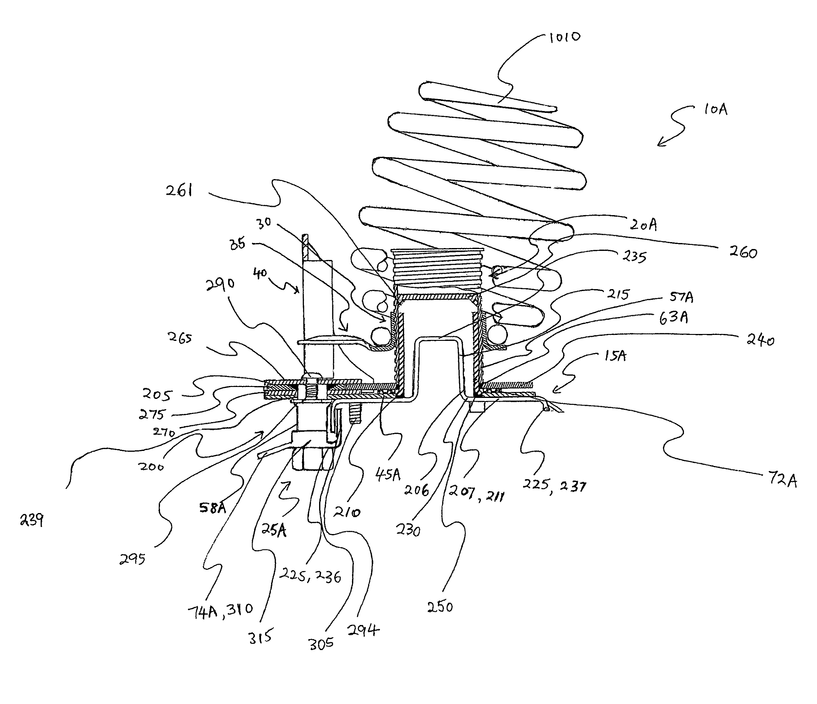
[0094]Referring to the drawings, various suspension height adjustment mechanisms are provided in accordance with embodiments of the present invention. The suspension height adjustment mechanisms may be used to vary the height of a vehicle's suspension, for example, in cars, trucks, SUVs or 4WDs.

[0095]It should be noted in the following description that like or the same reference numerals in different embodiments denote the same or similar features.

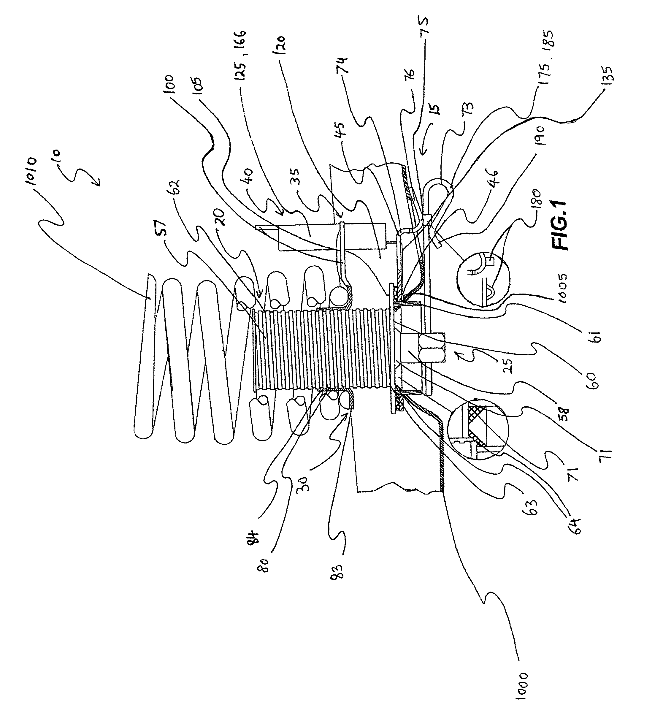
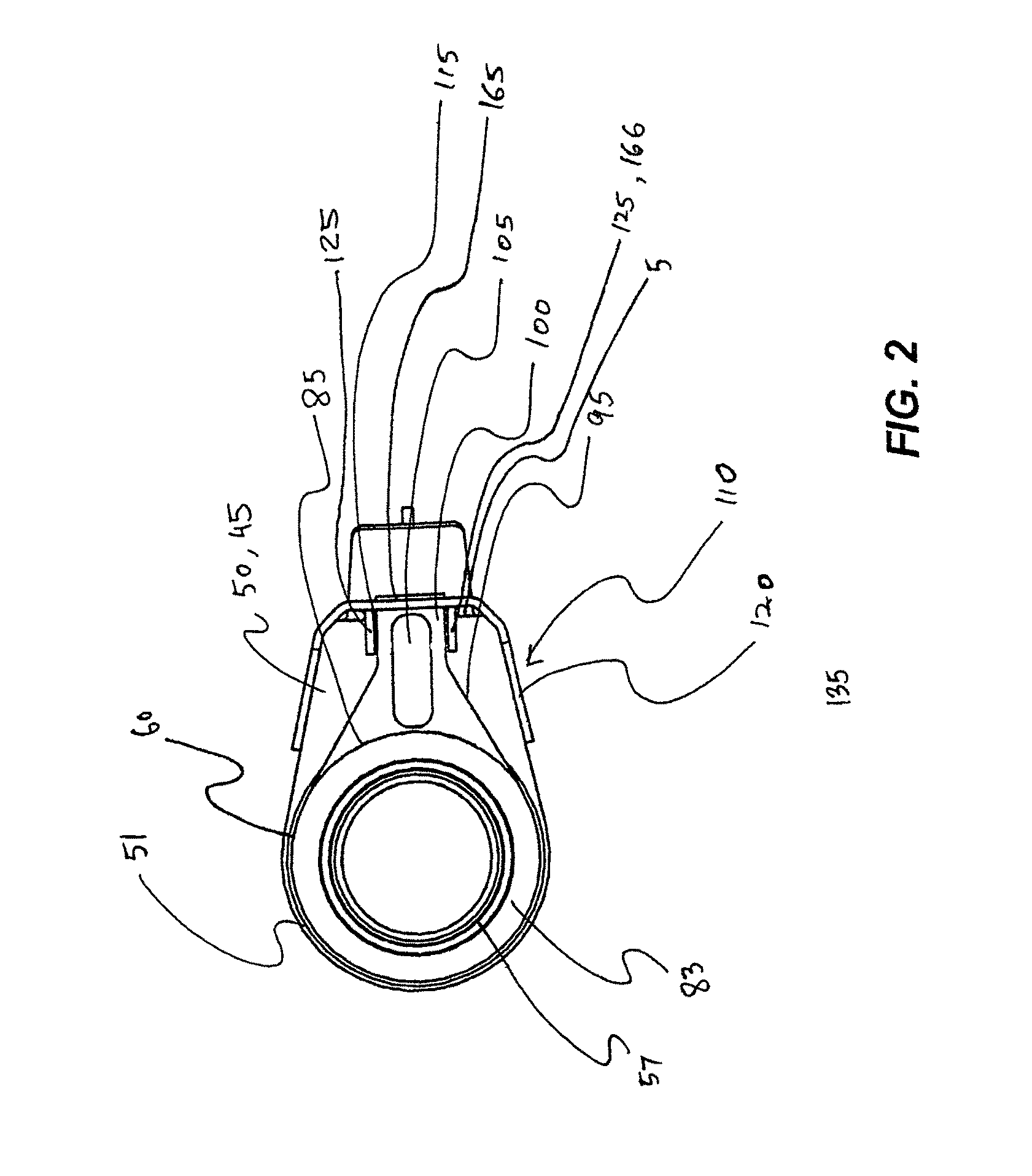
[0096]Referring to FIGS. 1 to 4, one embodiment of a suspension height adjustment mechanism 10 is shown and comprises a main body 15, a rotatable assembly 20, a tool engagement portion 25, a spring support 30, an anti-rotation means 35 on the spring support 30 and a corresponding anti-rotation means 40 mounted to the main body 15.

[0097]The rotatable assembly 20 is rotatably mounted to the main body 15 but translationally fixed with respect to the main body 15. The main body 15 comprises a base 45 with a substantially circular aperture 46. ...


PUM


Abstract

This disclosure relates to a suspension height adjustment mechanism comprising a main body, a rotatable assembly being rotatably mounted to the main body and having a first threaded portion, a tool engagement portion for rotating the rotatable assembly, a spring support having a second threaded portion engaging the first threaded portion, an anti-rotation means on the spring support adapted to cooperate with a corresponding anti-rotation means on the main body to prevent rotation of the spring support with respect to the main body, such that, in use, rotation of the tool engagement portion causes the spring support to axially translate along the rotatable assembly, thus adjusting the height of the suspension. This disclosure also relates to a vehicle suspension system comprising the suspension height adjustment mechanism and to a vehicle comprising the vehicle suspension system.

Description

FIELD OF THE INVENTION[0001]The present invention relates to vehicle suspension systems and in particular to a suspension height adjustment mechanism.[0002]The invention has been developed primarily for use with cars, trucks, SUVs, 4WDs and motorcycles and will be described hereinafter with reference to these applications. However, it will be appreciated that the invention is not limited to these particular fields of use. For example, the suspension height adjustment mechanism could be used on aircraft undercarriage or on armored vehicles.[0003]The invention can be used in conjunction with any suitable suspension systems, including independent arms, struts, semi-trailing arms and trail arm suspension arrangements.BACKGROUND OF THE INVENTION[0004]Varying the height of a vehicle's suspension is a common aftermarket modification. Height adjustment can be achieved by adjusting the height of the springs by a mechanical arrangement or in the case of pneumatic or hydraulic suspension arran...

Claims


Application Information

Patent Timeline
Patent Type & Authority Patents(United States)
IPC IPC(8): B60G17/00
CPCB60G17/021B60G2202/12B60G2202/42B60G2204/419
Inventor MCINTYRE, KEVIN JOSEPH
Owner MCINTIRE KEVIN JOSEPH
Why Eureka
Try Eureka