Multiple ultrasound beams transmitting and receiving method and apparatus

a multi-beam, ultrasound technology, applied in the field of multi-beam ultrasound beam transmitting and receiving methods and apparatuses, can solve the problems of image quality and frame rate, existing ultrasound imaging technologies are confronted with a problem, unfavorable 3d imaging effect, etc., and achieve the effect of enhancing the imaging frame rate of the ultrasound diagnostic system

Active Publication Date: 2012-01-03
SHENZHEN MINDRAY BIO MEDICAL ELECTRONICS CO LTD
View PDF27 Cites 38 Cited by
  • Summary
  • Abstract
  • Description
  • Claims
  • Application Information

AI Technical Summary

Benefits of technology

[0022]The technical problem to be solved by the embodiments of the invention is to provide a multi-beam receiving method and apparatus, which achieves a higher lateral resolution at a lower hardware cost, and addresses the disadvantages of the above existing technologies.
[0023]The invention achieves this object by using a synthetic aperture technique to overcome a low lateral resolution, and using multiple beam technique to increase the frame rate.
[0044]Compared to the existing technologies, the advantages of the multi-beam transmitting and receiving method and apparatus for an ultrasound diagnostic system according to the embodiments of the invention are that the merits of the synthetic aperture and the distortion elimination with the multi-beam technique are combined, thereby enhancing the imaging frame rate of the ultrasound diagnostic system while still promising a desired lateral resolution.

Problems solved by technology

Limitation in the imaging speed causes unfavorable effect to the 3D imaging.
The existing ultrasound imaging technologies are confronted with a problem of how to balance the image quality and the frame rate.
There is a conflict between the frame rate and the image quality.
In addition to the transmission of a fat beam, another technical challenge confronting the multi-beam reception technique is how to efficiently eliminate distortion of the receive scan lines, which is caused because the receive scan lines are located asymmetrically with respect to the sound field.
However, although the above mentioned existing technology may correct distortion, it is realized at the cost of a reduced lateral resolution, because a fat beam has to be transmitted in order to balance energy, which causes the lateral resolution of the sound field to be reduced.
To compensate for the decrease of resolution, a large receive aperture may be used, which, however, increases hardware cost.

Method used


Image

  • Multiple ultrasound beams transmitting and receiving method and apparatus
  • Multiple ultrasound beams transmitting and receiving method and apparatus
  • Multiple ultrasound beams transmitting and receiving method and apparatus

Examples


Embodiment Construction

[0050]The apparatus and method according to the embodiments of the invention will be described hereunder in details with reference to the accompanying drawings and the embodiments illustrated in the accompanying drawings.

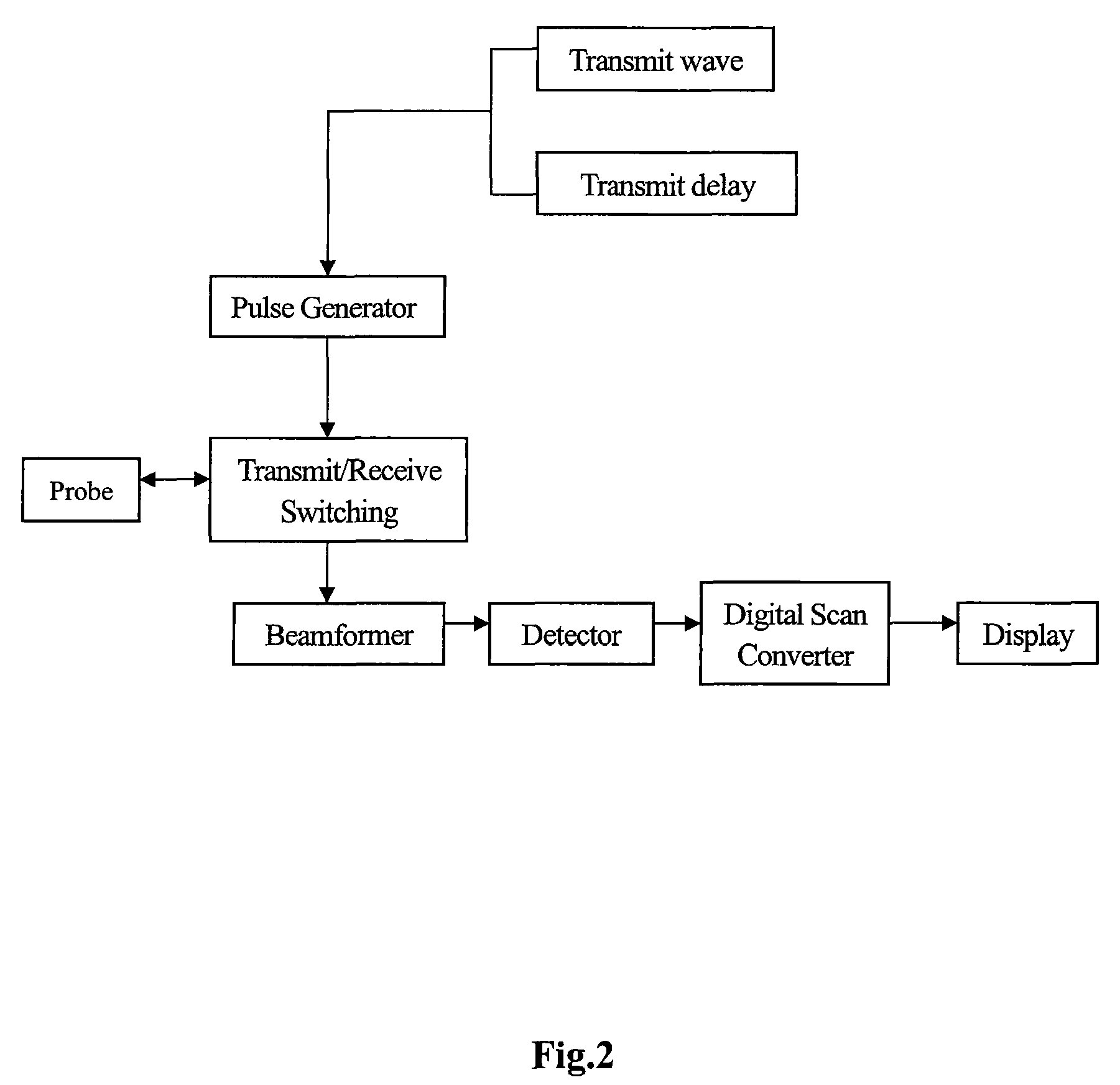
[0051]FIG. 2 is a functional block diagram of an ultrasound imaging system which can be used to implement the embodiments of the invention. A pulse generator activates each array element of a probe to transmit a beam based on the transmit wave and transmit delay. A tissue reflects the transmitted beam as echoes, and the echoes, having been received and detected by the array elements at the receive aperture of the probe, are transmitted to a beamformer, which combines the echoes into data of single scan line based on receive delays and apodization. The envelope data of the scan line is thereafter derived from the data of the scan line by a detector. The detector is also operable to perform sub-sampling and logarithmic compression, etc. Subsequently, a digital scan co...


PUM


Abstract

This present application describes a multiple ultrasound beams transmitting and receiving method, comprising: transmitting a first fat beam along a first transmit line with a first transmit aperture; receiving echo of the first fat beam with a first receive aperture and forming data of a first group of receive lines; transmitting a second fat beam along a second transmit line with a second transmit aperture; receiving echo of the second fat beam with a second receive aperture and forming data of a second group of receive lines; constructing a full receive aperture by combining the first receive aperture and the second receive aperture, the full receive aperture centered in the area covering the first group of receive lines and the second group of receive lines; weighting a data of a receive line of the first group and a data of a receive line of the second group collinear with said receive of the first group respectively, and summing two weighted data.

Description

RELATED APPLICATIONS[0001]The present application claims the priority of the Chinese Patent Application No. CN200610157174.4, entitled “MULTI-BEAM TRANSMITTING AND RECEIVING METHOD IN AN ULTRASOUND DIAGNOSTIC SYSTEM AND APPARATUS FOR THE SAME”, filed on Nov. 28, 2006, which is incorporated herein by reference.TECHNICAL FIELD[0002]The invention relates to imaging technologies for medical ultrasound diagnostic systems, more particularly to a multiple ultrasound beams transmitting and receiving method and apparatus.BACKGROUND TECHNOLOGY[0003]It is important to study the fast imaging technique of an ultrasound diagnostic system. Implementation of the fast imaging lays a solid foundation for realizing some more advanced technologies. One of the advantages relates to a higher data rate. Larger amount of information obtained in a unit time guarantees a better and more accurate image analysis, thus enabling better executions of various techniques. In particular, the fast imaging technique p...

Claims


Application Information

Patent Timeline
Patent Type & Authority Patents(United States)
IPC IPC(8): A61B8/00
CPCG01S7/52046G01S7/52085G01S7/52095G01S15/8927G10K11/345G01S15/8993
Inventor YAO, BINJIANG, YONGHU, QINJUNYANG, BO
Owner SHENZHEN MINDRAY BIO MEDICAL ELECTRONICS CO LTD
Why Eureka
Try Eureka