
Method for forming phase grating

a phase grating and grating technology, applied in the field of forming a phase grating, can solve the problems of difficult control of the cross section of the pattern, low yield, and unoptimized focus capability of such planar gratings, and achieve excellent optical properties and focus capability, and achieves convenient and convenient operation.

Active Publication Date: 2012-01-10
UNITED MICROELECTRONICS CORP
View PDF8 Cites 3 Cited by
  • Summary
  • Abstract
  • Description
  • Claims
  • Application Information

AI Technical Summary

Benefits of technology

The present invention proposes a Fresnel-Lens type phase grating with better focus capability. The grating has a unique structure with rings and columns that are concentric and have different heights, resulting in excellent optical properties and focus capability. The method for forming the grating is simple and convenient, and avoids the traditional complicated processes. The grating can be easily obtained by selective etching and has been found to have excellent optical properties and focus capability. The technical effects of the invention are improved focus capability and simplified manufacturing process.

Problems solved by technology

The problems of this method are, for example, difficult to control the cross section of the patterns and low yield.
However, U.S. Pat. No. 5,132,843 does not disclose the substrate is made of what material or a plurality of concentric circles is formed by which methods on the substrate.
The focus capability of such planar gratings is not optimal.

Method used


Image

  • Method for forming phase grating
  • Method for forming phase grating
  • Method for forming phase grating

Examples


Embodiment Construction

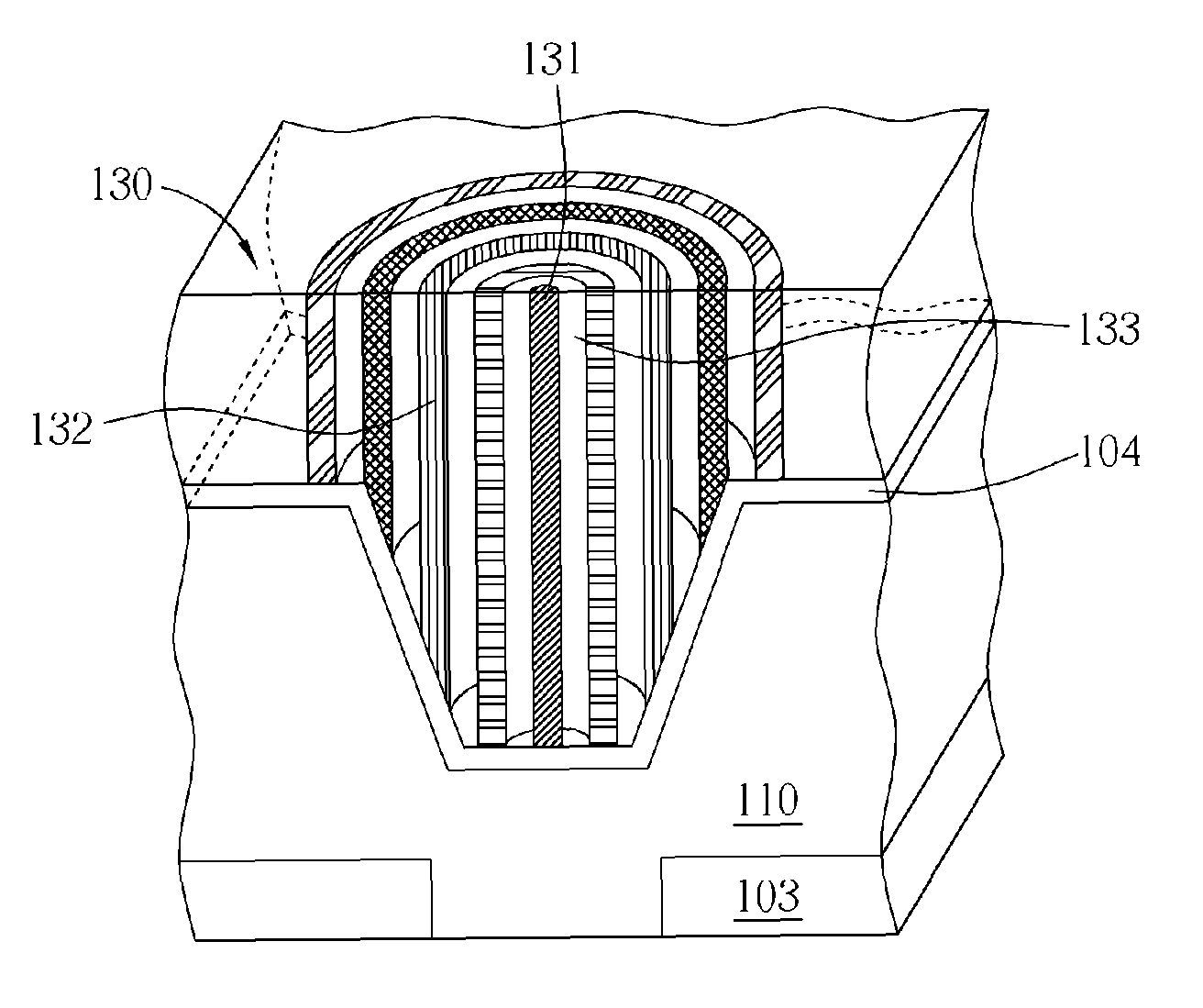
[0018]The gist of the present invention provides a method to practice various phase gratings to obtain a Fresnel-Lens type phase grating of better focus capability. Such Fresnel-Lens type phase grating of the present invention not only possesses excellent focus capability but also avoids the disadvantages of the traditional complicated processes to form semiconductor optical elements, such as micro lens or color filters, which is particularly suitable for the micro optical elements, such as the CMOS image sensor (CIS) in the semiconductor field.

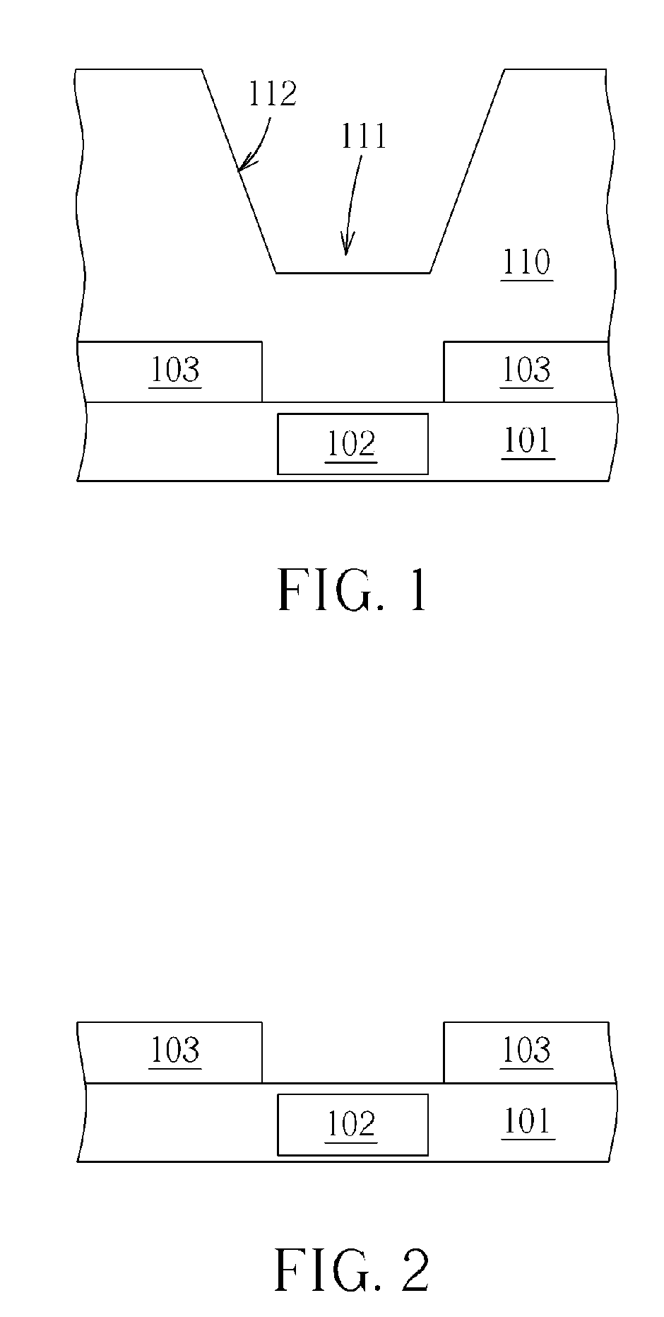
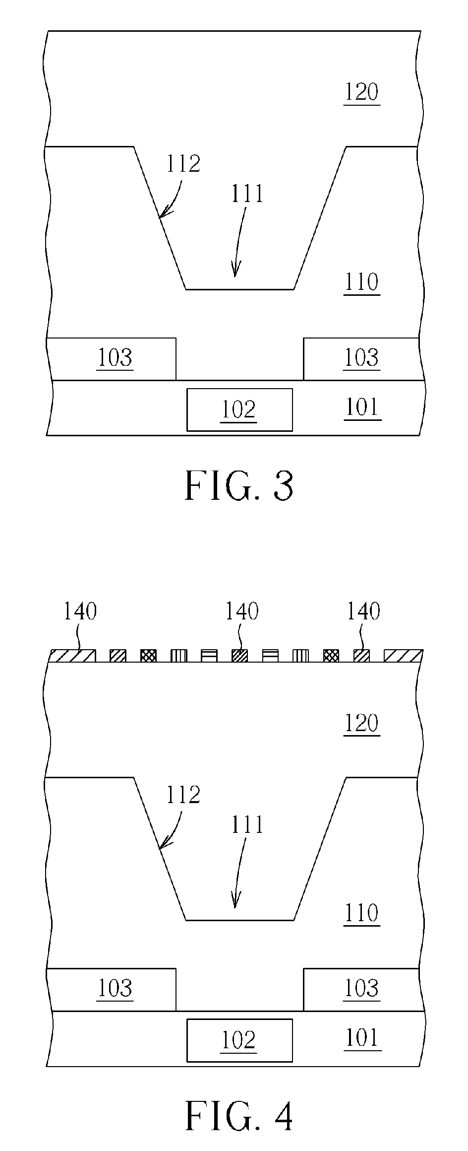
[0019]The present invention first provides a method for forming a phase grating. FIGS. 1-7 illustrate a preferred embodiment of the method for forming a phase grating of the present invention. As shown in FIG. 1, first a substrate 101 is provided. The substrate 101 may include Si. In addition, the substrate 101 further includes a micro optical element, such as an image sensor element 102. A first dielectric layer 110 is formed on the substrat...


PUM

PropertyMeasurementUnit
heightaaaaaaaaaa
phaseaaaaaaaaaa
dielectricaaaaaaaaaa

Abstract

A method for forming a phase grating is disclosed. First, a substrate is provided. Second, a first dielectric layer with a tapered recess or bulge is formed on the substrate. Later, a second dielectric layer is formed to fill the tapered recess and to cover the first dielectric layer. Afterwards, the second dielectric layer is selectively etched to form the phase grating. The phase grating includes a column and multiple rings. The column and multiple rings are concentric and the multiple rings are disposed on the tapered side so that the height of each ring is different.

Description

BACKGROUND OF THE INVENTION[0001]1. Field of the Invention[0002]The present invention relates to a method for forming a phase grating. In particular, the present invention relates to a method to manufacture the rings of the phase grating to have different height by selective etching.[0003]2. Description of the Prior Art[0004]Grating is an optical element made of periodical fine patterns. The patterns constituting the grating may be the change of transmittance, thickness or index of refraction. Among which, the grating made of change of thickness or index of refraction modulates the phase of the light to have diffraction. It is therefore called “phase grating”.[0005]The substrate for the grating is usually glass or plastics. The transmittance, thickness or index of refraction of the surface is then somehow changed. For example, fine patterns are engraved on the glass substrate by mechanical methods to obtain a reflective grating. Besides, most of the gratings made of plastics are thi...

Claims


Application Information

Patent Timeline
Patent Type & Authority Patents(United States)
IPC IPC(8): B29D11/00
CPCB29D11/00269G02B5/1871G02B5/1857G02B2005/1804
Inventor SHIU, JIAN-BIN
Owner UNITED MICROELECTRONICS CORP
Learn More