Ion radiation therapy system with rocking gantry motion

a radiation therapy system and gantry technology, applied in the field of radiotherapy systems, can solve the problems of not being able to achieve the uniform dose deposited by the proton beam along the entrance path of the beam, requiring the construction of a special compensator, and being fast and yet less precise. achieve the effect of improving the dose conformity, reducing cold spots, and long treatment tim

Active Publication Date: 2012-01-10
WISCONSIN ALUMNI RES FOUND
View PDF60 Cites 59 Cited by
  • Summary
  • Abstract
  • Description
  • Claims
  • Application Information

AI Technical Summary

Benefits of technology

[0008]The present invention provides a treatment system that employs a fan beam of ions and separately modulates “beamlets” within the fan. The fan is rotated about the patient in a partial arc during the modulation process. This partial arc substantially improves the conformity of the dose to the tumor over that provided by the SOBP approach while reducing cold spots and the long treatment times associated with the MSS approach. The partial arc further greatly simplifies the treatment mechanism and the positioning of bulky neutron shields. The partial arc provides conformity of dose to the tumor that is nearly equal to that obtained from a complete arc of 360° while eliminating dose to sensitive tissue on the distal side of the patient.

Problems solved by technology

Further, the dose deposited by a proton beam is not uniform along the entrance path of the beam, but rises substantially to a “Bragg peak” near a point where the proton beam stops within the tissue.
This treatment approach essentially treats the entire tumor at once and, thus, is fast and yet less precise and requires the construction of a special compensator.
This approach is potentially very accurate, but because the tumor is treated in many successive exposures, this approach is much slower than the SOBP approach.
Further the small spot sizes create the risk of uneven dose placement or “cold spots” between the treatment spots, something that is exacerbated if there is any patient movement between exposures.

Method used


Image

  • Ion radiation therapy system with rocking gantry motion
  • Ion radiation therapy system with rocking gantry motion
  • Ion radiation therapy system with rocking gantry motion

Examples


Embodiment Construction

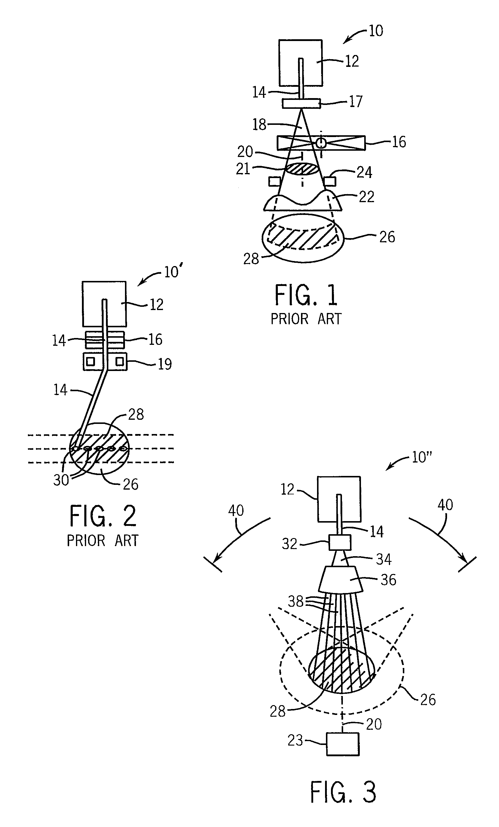
[0049]Referring now to FIG. 1, a conventional ion radiation therapy system 10 employing the SOBP approach described above provides an ion source 12 producing a pencil beam 14 of ions traveling along an axis 20.

[0050]The pencil beam 14 may be received by a foil 17 scattering the pencil beam into a cone beam 18 having a circular cross-section 21. The energy of the ions in the cone beam 18 is then received by a rotating wedge propeller placing a material of varying thickness in the cone beam 18 and acting as a range shifter 16 continuously changing the energy and thus range of penetration ions into tissue.

[0051]The cone beam 18 then passes through a collimator 24 approximating the outline of the tumor and a compensator 22 tailor-made for the particular tumor being treated after which the cone beam 18 is received by the patient 26 to produce a treatment pattern 28. As noted, this treatment approach simultaneously treats the entire volume of the tumor and is therefore relatively quick, b...


PUM


Abstract

A radiation therapy system for heavy ions employs a rocking motion of a fan beam used to treat the patient, the fan beam having individually modulated beamlets, the rocking limited in angular extent to provide improved conformance of the dose to a tumor while shielding distal tissue from radiation.

Description

CROSS-REFERENCE TO RELATED APPLICATIONS[0001]This application claims the benefit of U.S. Provisional Application 60 / 891,859, filed Feb. 27, 2007, and PCT Application PCT / US2008 / 055070, filed Feb. 27, 2008, the disclosures of which are incorporated herein by reference.STATEMENT REGARDING FEDERALLY SPONSORED RESEARCH OR DEVELOPMENT[0002]This invention was made with United States government support awarded by the following agency: NIH CA088960. The United States government has certain rights in this invention.BACKGROUND OF THE INVENTION[0003]The present invention relates to radiotherapy systems, such as those using ions like protons, for the treatment of cancer and, in particular, to a system providing improved treatment speed and accuracy.[0004]External beam radiation therapy may treat a tumor within the patient by directing high-energy radiation in one or more beams toward the tumor. Recent advanced external beam radiation systems, for example, as manufactured by Tomotherapy, Inc., t...

Claims


Application Information

Patent Timeline
Patent Type & Authority Patents(United States)
IPC IPC(8): A61N5/10A61N5/02
CPCA61N5/10A61N5/103A61N2005/1087A61N2005/1095A61N5/1081
Inventor MACKIE, THOMAS R.KISSICK, MICHAEL WILLIAMFLYNN, RYAN THOMAS
Owner WISCONSIN ALUMNI RES FOUND
Why Eureka
Try Eureka