Sound channel for a hearing apparatus and corresponding production process

a technology for hearing apparatuses and sound channels, applied in electrical apparatus, deaf-aid sets, frequency/directions obtaining arrangements, etc., can solve problems such as complicated turning and milling parts, and achieve the effect of low melting point, easy melting or burning ou

Inactive Publication Date: 2012-01-10
SIEMENS MEDICAL EQUIPMENT
View PDF16 Cites 7 Cited by
  • Summary
  • Abstract
  • Description
  • Claims
  • Application Information

AI Technical Summary

Benefits of technology

[0010]The object of the present invention consists in providing a sound channel for a hearing apparatus, which has a relatively complex form and can consequently be easily produced and is mechanically stable.
[0013]During the production using injection molding technology, the sound channel is advantageously no longer restricted in respect of its shape such that it only has two differently curved sections, with which it is possible to ensure that the casting mold parts can be drawn from the newly injected sound channel in both longitudinal directions which are opposite to one another. Since the negative located inside the newly injected sound channel is not extracted but is instead melted or burnt out, almost any forms of the negative are possible. Injection molding simultaneously provides for precise and mechanically stable injection molded elements.
[0016]It is particularly advantageous if the negative is a plastic injection-molded part. Plastic negatives of this type can, due to their low melting point, be easily melted or burnt out of the metal or ceramic sound channels.
[0017]One or several nozzles, cavities and such like can be molded into or onto the sound channel. Nozzles or cavities of this type can be advantageous for acoustic reasons and do not present any problems when demolding the injection-molded parts, here the melting or burning process of the negative.
[0018]The sound channel can also have at least one branching. This can also provide acoustic advantages and also present no problems in respect of demolding.

Problems solved by technology

These are complicated turning and milling parts, which in most cases subsequently still have to be bent.

Method used


Image

  • Sound channel for a hearing apparatus and corresponding production process
  • Sound channel for a hearing apparatus and corresponding production process
  • Sound channel for a hearing apparatus and corresponding production process

Examples


Embodiment Construction

[0025]The exemplary embodiments illustrated in more detail below represent preferred embodiments of the present invention.

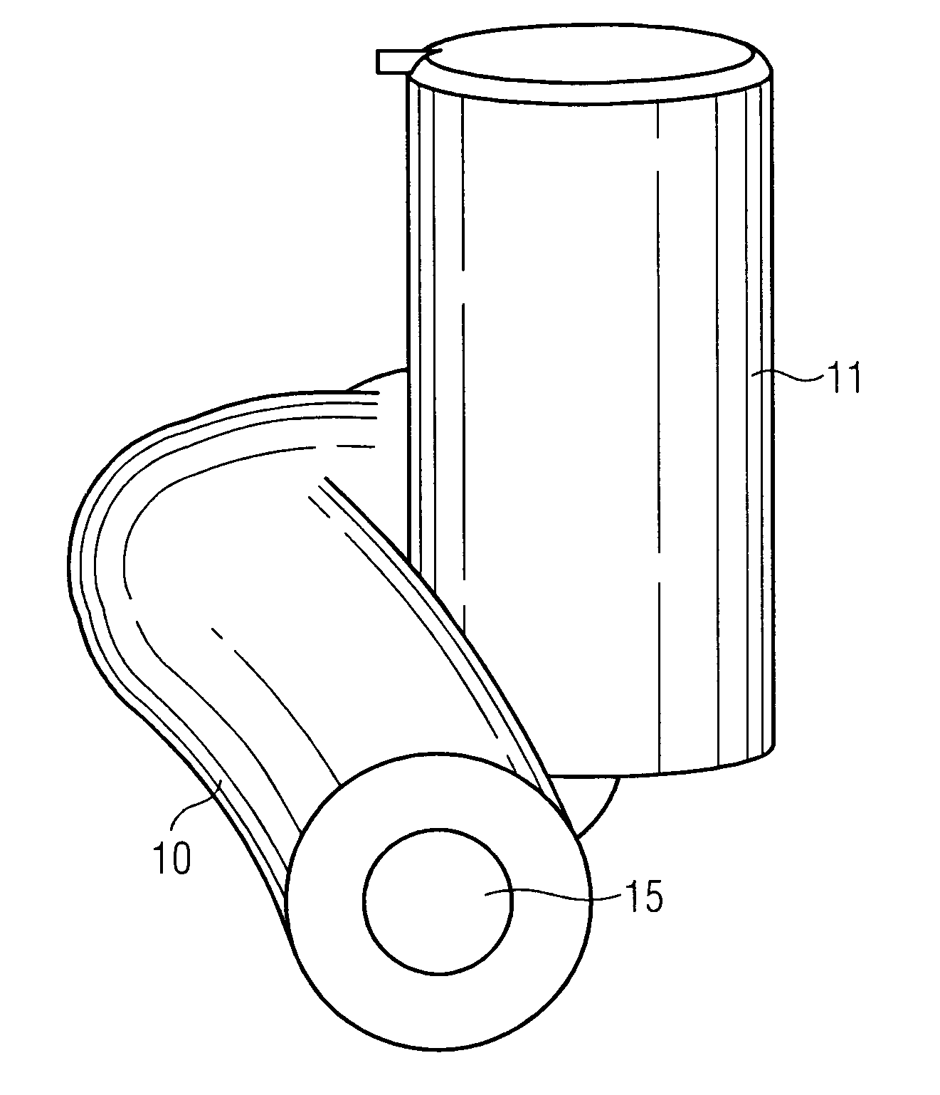
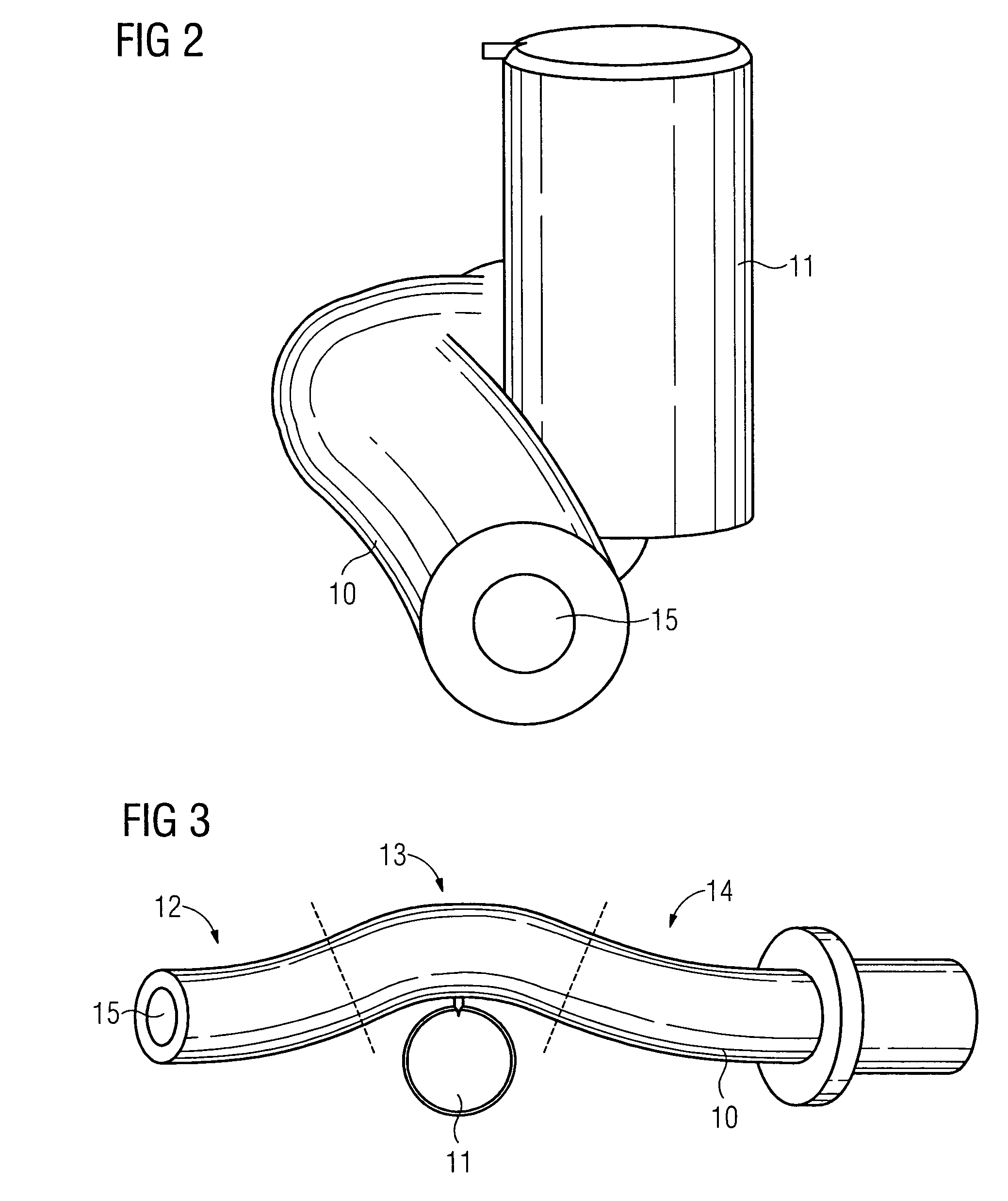
[0026]FIG. 2 shows a sound channel 10, which is wound around an obstacle 11. A situation of this type occurs particularly in hearing devices if the volume of the hearing device is to be reduced and an obstacle 11 lies here in the alignment of the sound channel 10. This may be the case not only with sound channels, which show the connecting element between the wearing hook and receiver in an BTE hearing device, but instead also in sound channels between a sound entry opening and a microphone for instance.

[0027]FIG. 3 shows a plan view of the sound channel 10 and the obstacle 11. The sound channel 10 is subdivided into three sections 12, 13 and 14 purely for orientation purposes. Each of these sections 12, 13 and 14 has a different curvature. In particular, the curvature in the middle section 13 deviates from one of the two outer sections 12 and 14. In the present ...


PUM


Abstract

A mechanically more stable and more complexly molded sound channel is to be provided for a hearing apparatus. Provision is made to this end for a sound channel, which has three sections in the longitudinal direction, the middle section of which has a different curvature or a larger internal circumference than the two outer sections, to be produced by injection molding. Here a negative of the sound channel is fixed within the injection molded form, with the negative consisting of a first material. The injection molded form with a second material, which has a higher melting point than the first material, is then extruded. The negative is then melted or burnt out of the cast sound channel. Very complex sound channel forms, for instance also with cavities and branching, can be realized in this way.

Description

CROSS REFERENCE TO RELATED APPLICATIONS[0001]This application claims priority of German application No. 10 2007 044 550.6 DE filed Jul. 5, 2004, which is incorporated by reference herein in its entirety.FIELD OF INVENTION[0002]The present invention relates to a method for producing a sound channel for a hearing apparatus. The present invention also relates to a corresponding sound channel for a hearing apparatus. The term “hearing apparatus” is understood here to mean in particular a hearing device but also any other device for outputting sound which can be worn on or in the ear, like for instance a headset, earphones and such like.BACKGROUND OF INVENTION[0003]Hearing devices are wearable hearing apparatuses which are used to assist the hard-of-hearing. In order to accommodate numerous individual requirements, various types of hearing devices are available such as behind-the-ear (BTE) hearing devices, hearing device with an external receiver (RIC: receiver in the canal) and in-the-e...

Claims


Application Information

Patent Timeline
Patent Type & Authority Patents(United States)
IPC IPC(8): H04R25/00
CPCH04R25/658H04R1/34
Inventor FREELS, BJORNKRAL, HOLGER
Owner SIEMENS MEDICAL EQUIPMENT
Why Eureka
Try Eureka