Multi-core holey fiber and optical transmission system

a multi-core holey fiber and optical transmission technology, applied in multiplex communication, cladded optical fibres, instruments, etc., can solve the problems of leaking of a portion of the transmitted optical signal in one core, crosstalk deterioration of multi-core holey fibers between optical signals,

Active Publication Date: 2012-01-10
FURUKAWA ELECTRIC CO LTD
View PDF14 Cites 233 Cited by
  • Summary
  • Abstract
  • Description
  • Claims
  • Application Information

AI Technical Summary

Problems solved by technology

However, multi-core holey fibers experience crosstalk deterioration between optical signals because interference among optical signals in a plurality of cores causes some portion of the transmitted optical signal in one core to leak into another core(s).

Method used


Image

  • Multi-core holey fiber and optical transmission system
  • Multi-core holey fiber and optical transmission system
  • Multi-core holey fiber and optical transmission system

Examples


first embodiment

of the Present Invention

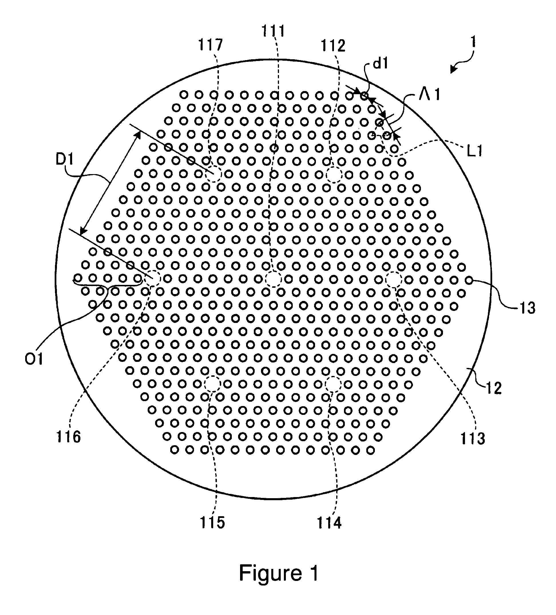
[0032]FIG. 1 shows a schematic cross-sectional drawing of a multi-core HF related to a first embodiment of the present invention. As shown in FIG. 1, the multi-core HF comprises seven cores 111˜1117 arranged separately from each other and a cladding 12 that surrounds the cores 111˜117. The core 111 is positioned approximately at the center of the fiber and the other cores 112˜117 are positioned at apexes of a regular hexagon with the core 111 as the center. Also, the cladding 12 has a plurality of the holes 13 positioned periodically around the cores 111˜117. The holes 13 are positioned to form triangular-shaped lattices, L1, and to shape layers of regular hexagons to surround cores 111˜117. The cores 111˜117 and the cladding 12 are made from pure silica glass, which does not include any refractive index control dopants.

[0033]If the diameters, d1, of the holes 13 are d [μm] and a lattice constant, Λ1, of the triangular lattice, L1, the distance between the cl...

second embodiment

of the Present Invention

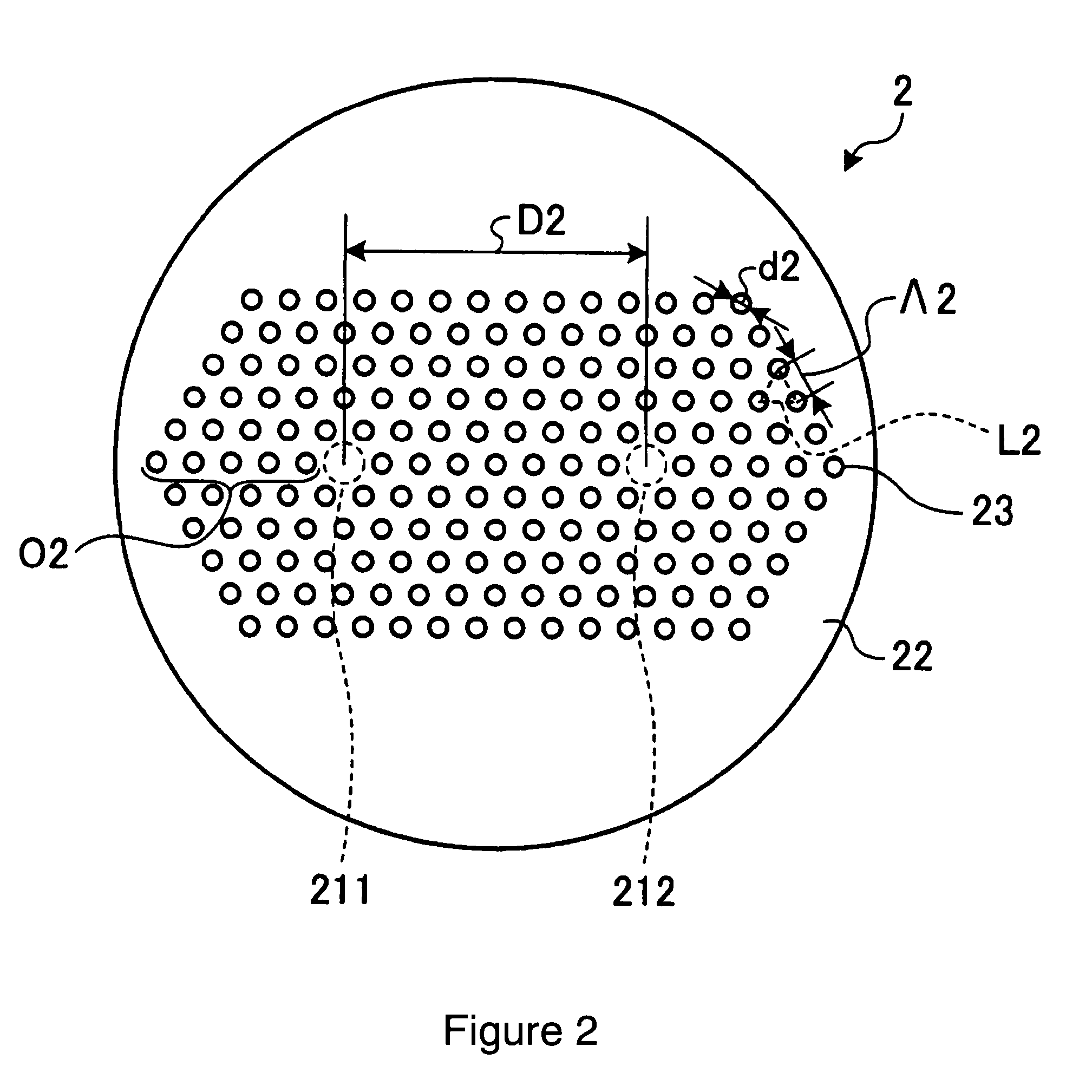
[0044]Below, a second embodiment of the present invention is disclosed. FIG. 2 shows a schematic cross-sectional drawing of a multi-core HF related to the second embodiment of the present invention. As shown in FIG. 2, the multi-core HF 2 comprises two cores 211, 212 arranged separately from each other and a cladding 22 positioned to surround the cores 211, 212. The cores 211, 212 are positioned approximately symmetric to each other with respect to the center of the multi-core HF 2. Also, the cladding 22 has a plurality of holes 23 positioned periodically around the cores 211, 212. The holes 23 are positioned to form triangular lattices L2 and to form layers of hexagons that surround the cores 211, 212. The cores 211, 212 and the cladding 22 are made from the pure silica glass.

[0045]If the diameters, d2, of the holes 23 are d [μm] and a lattice constant A2 of the triangular lattice, L2, is Λ [μm], then Λ is 6 μm and d / Λ is 0.43. Also, for the core 211, the ou...

third embodiment

of the Present Invention

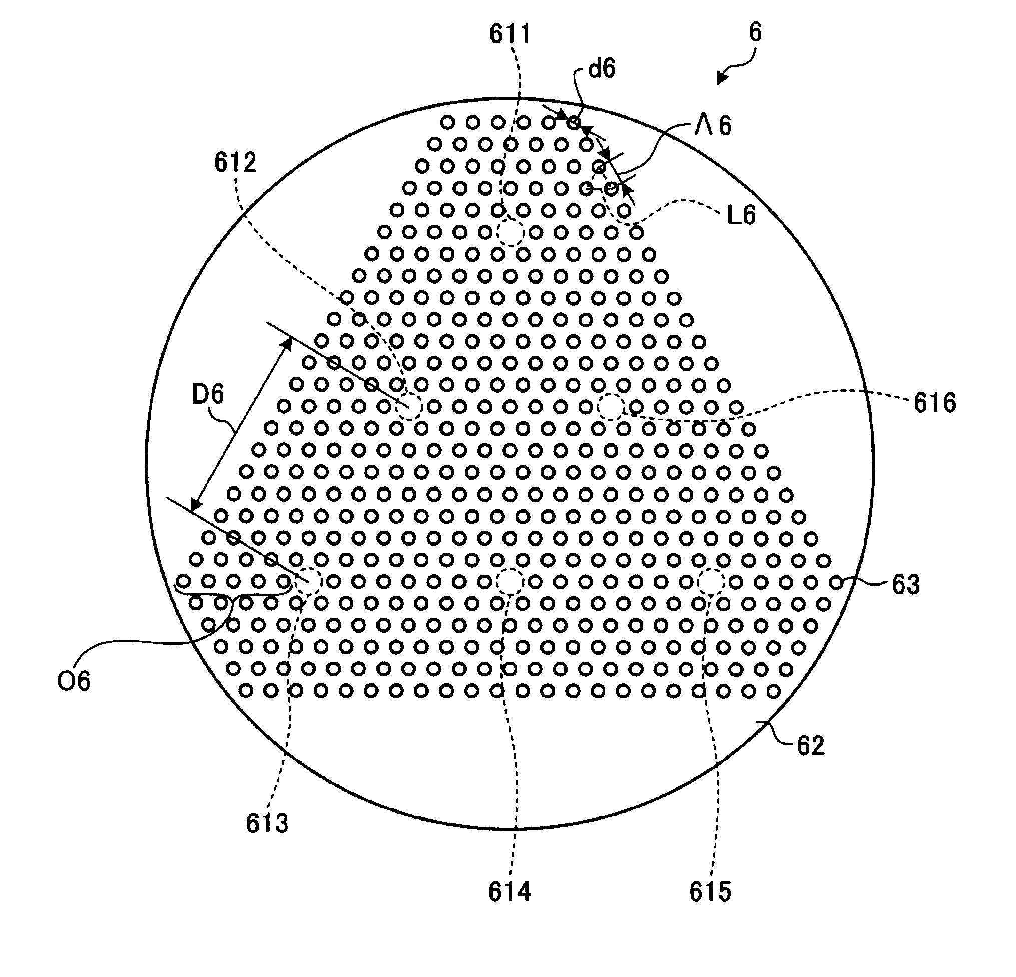
[0047]Below, a third embodiment of the present invention is disclosed. FIG. 3 shows a schematic cross-sectional drawing of a multi-core HF related to the third embodiment of the present invention. As shown in FIG. 3, the multi-core HF 3 comprises three cores 311˜313 arranged separately from each other and a cladding 32 surrounds the cores 311˜313. The cores 311˜313 are positioned at the apexes of a regular triangle, which has a center at the center of the multi-core HF 3. Also, the cladding 32 has a plurality of holes 33 positioned periodically around the cores 311˜313. The holes 33 are positioned to form triangular lattices L3 and to form layers of hexagons that surround the cores 311˜313. The cores 311˜313 and the cladding 32 are made from pure silica glass.

[0048]If the diameters, d3, of the holes 33 are d [μm] and a lattice constant, Λ3, of the triangular lattice 3 is Λ [μm], then Λ is 6 μm and d / Λ is 0.43. Also, for the core 312, the outermost layers O3 c...


PUM


Abstract

A multi-core holey fiber with suppression of crosstalk deterioration among transmitted optical signals in a plurality of cores, and an optical transmission system using the fiber are disclosed. The multi-core holey fiber comprises a plurality of cores arranged separately from each other, and a cladding surrounding the plurality of cores wherein the cladding has plurality of holes arranged in a triangular lattice shape to create hole layers around the plurality of cores. Additionally, d / Λ is not more than 0.5, where Λ [μm] is lattice constant of the triangular lattice, d [μm] is diameter of each of the holes; a distance between adjacent cores is equivalent to not less than six hole layers; the cores arranged farthest from the center of the multi-core holey fiber is surrounded by not less three hole layers; and the sum of the coupling coefficients between the adjacent cores is not more than 1.6×10⁻⁵ / m.

Description

CROSS-REFERENCES TO RELATED APPLICATIONS[0001]This application claims the benefit of priority from Japanese Patent Application No. 2008-222806 filed Aug. 29, 2008, the entire contents of which is incorporated herein by reference.TECHNICAL FIELD[0002]The present invention relates to a multi-core holey fiber and an optical transmission system, which uses the multi-core holey fiber as an optical transmission line.BACKGROUND OF THE INVENTION[0003]Because of the developments in optical amplifiers and signal modulation / demodulation schemes, optical communication transmission capacity has increased rapidly. Also, because of the growth in Fiber-To-The-Home (FTTH), data demand has also increased, and it is necessary to increase transmission capacity even further in the future. One of the effective ways to increase transmission capacity is to increase the bandwidth of the used transmission wavelength band. And, as a way to increase the bandwidth, a holey fiber, which is a new type of an optic...

Claims


Application Information

Patent Timeline
Patent Type & Authority Patents(United States)
IPC IPC(8): G02B6/02
CPCG02B6/02042G02B6/02333G02B6/02347H04J14/02
Inventor IMAMURA, KATSUNORI
Owner FURUKAWA ELECTRIC CO LTD
Why Eureka
Try Eureka