Sampling apparatus and method

a sampling apparatus and sampling method technology, applied in the field of sampling apparatus and method, can solve the problems of insufficient guidance of the free strip end, difficult sampling, and inability to inspect readily, and achieve the effect of reliable sampling or cropping

Inactive Publication Date: 2012-01-17
PRIMETALS TECH AUSTRIA GMBH
View PDF8 Cites 5 Cited by
  • Summary
  • Abstract
  • Description
  • Claims
  • Application Information

AI Technical Summary

Benefits of technology

[0006]Proceeding from the prior art, an object of the invention is to make available an apparatus and a method which allow a reliable sampling or cropping of strips wound into bundles, while a reliable solution is to be offered even in the case of strips of greater firmness or thickness.

Problems solved by technology

The disadvantage of this, above all, is that the free strip length which the strip covers from the rear bearing roller, as seen in the direction of rotation, as far as the guide devices or the shears is very long, so that sufficient guidance of the free strip end is not reliably afforded.
Particularly where thicker and firm strips are concerned, this may lead to faults or make sampling more difficult.
Nor is inspection readily possible because of the position of the cut sample.

Method used


Image

  • Sampling apparatus and method
  • Sampling apparatus and method
  • Sampling apparatus and method

Examples


Embodiment Construction

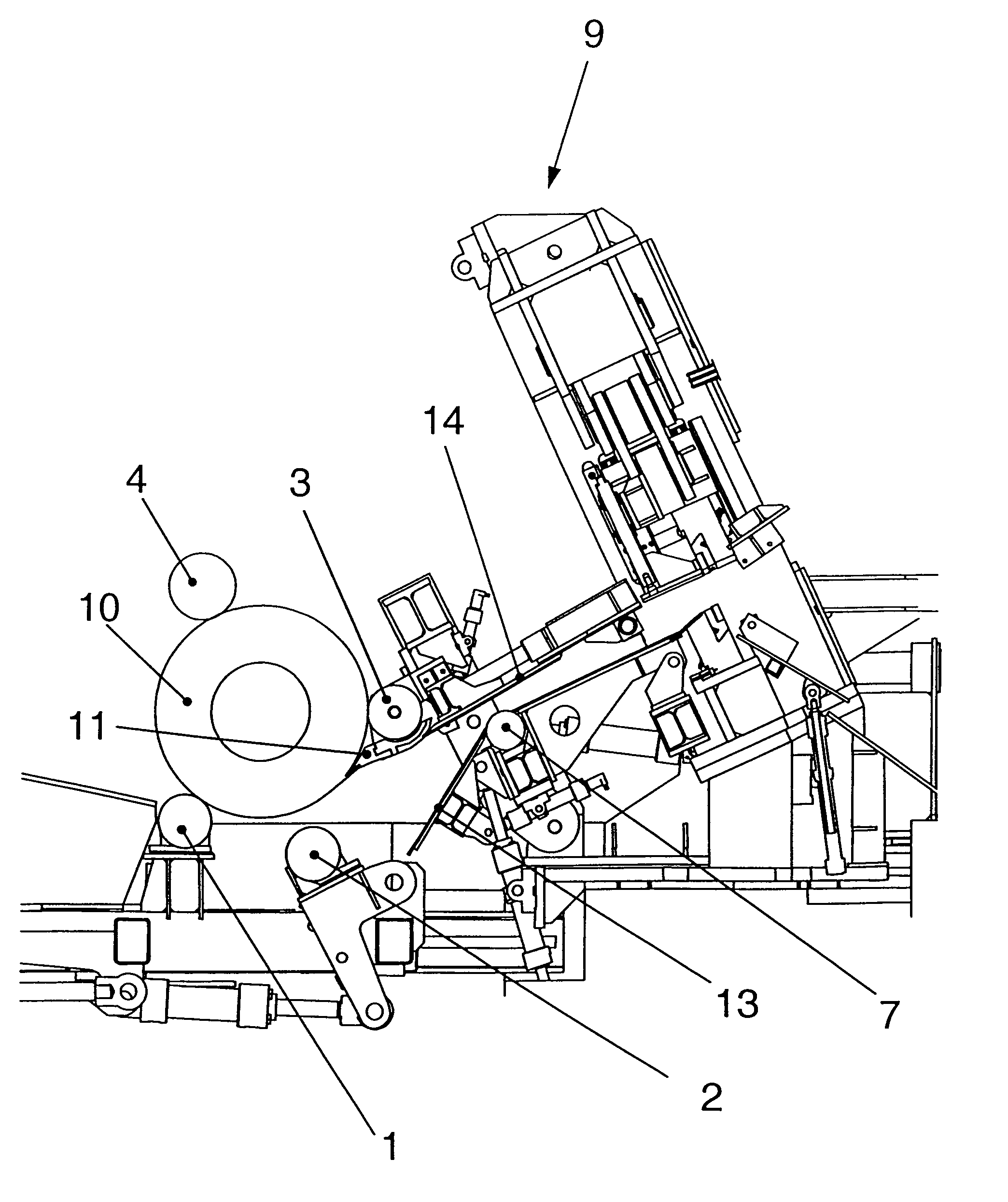
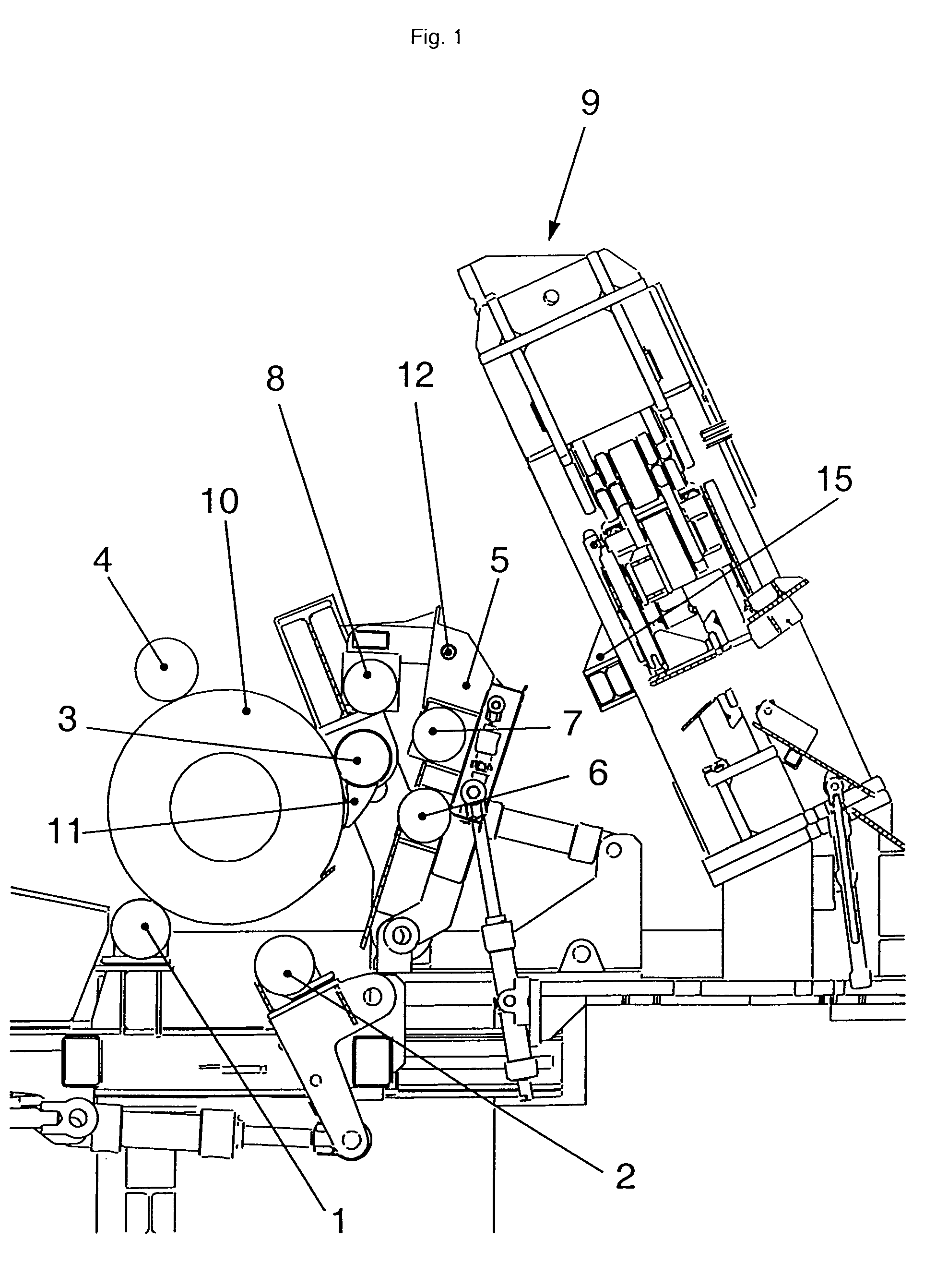
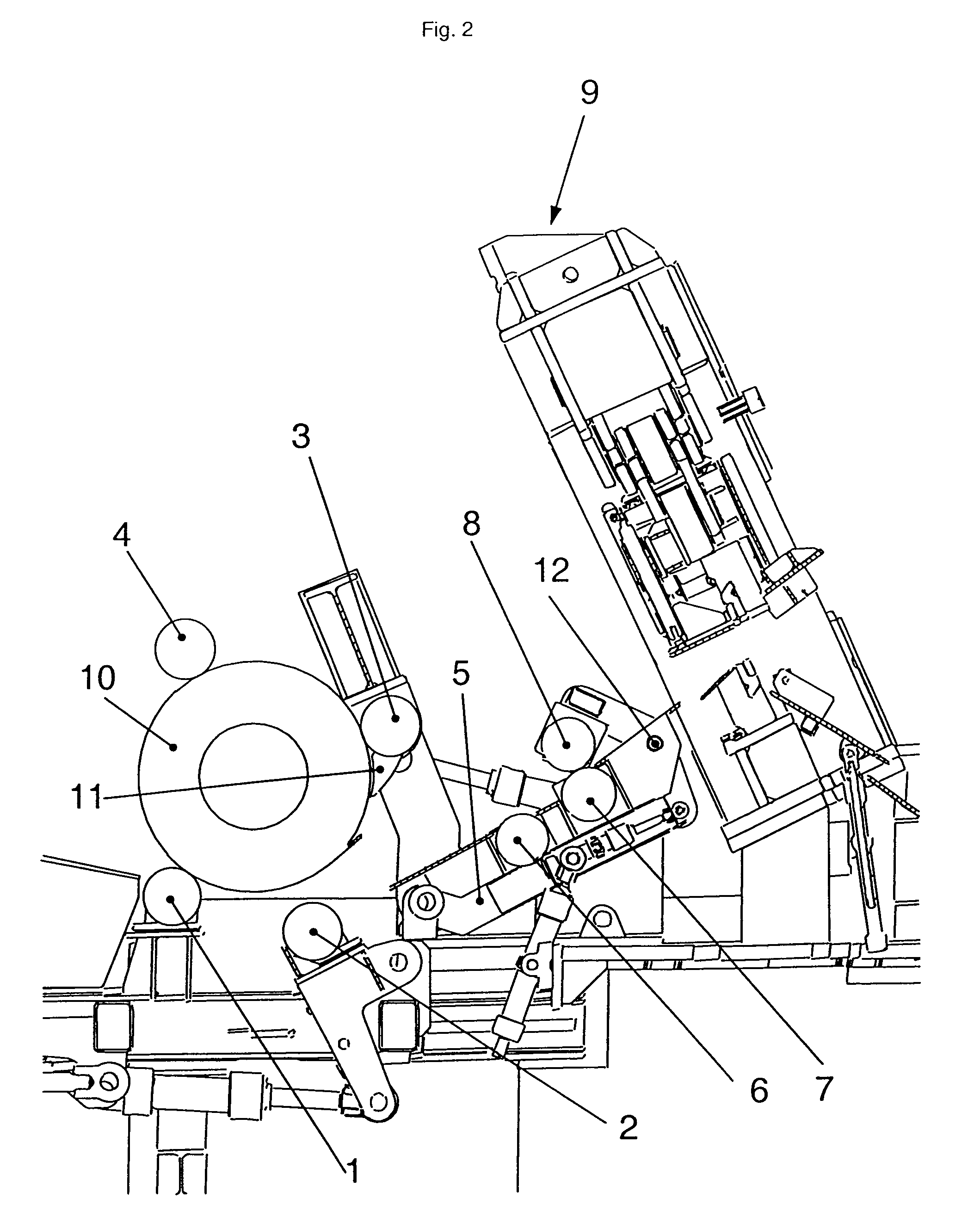
[0040]The apparatus according to the invention during the unwinding of the strip from the bundle (10) may be gathered from FIG. 1. The unwound strip end is not illustrated in the figures. The situation illustrated in FIG. 1 shows the already lowered bottom roller (2). The bundle (10) rests on the bottom roller (1) and the pivoted-in pressure roller (3). An additional pressure roller (4) may also optionally be provided, so that the bundle (10) is supported on its surface area, in each case approximately an arc angle of 120° between the lines of contact of the rollers on the surface area being advantageous. By virtue of the mounting on the rollers (1, 3, 4), on the one hand, a rotation of the bundle is possible and, on the other hand, the bundle (10) is reliably prevented from springing open. It is also possible to provide more than one additional pressure roller, so that the bundle can additionally be guided on its surface area.

[0041]It has proved advantageous to design one or more o...


PUM

PropertyMeasurementUnit
arc angleaaaaaaaaaa
diameteraaaaaaaaaa
surface areaaaaaaaaaaa

Abstract

The invention relates to an apparatus and a method for cropping the ends of or for separating test pieces from rolled strip wound into bundles. An apparatus is disclosed which, by means of an outwardly pivotable bottom roller (2) and guide devices (5, 6, 7, 8, 13, 14) for guiding the strip end to the shears, also makes it possible to process strips which are thicker or of greater firmness and are wound into bundles (10). Furthermore, a method is specified, which allows a reliable sampling and, if appropriate, inspection of the sample from strips wound into bundles, a closed bundle being obtained again after sampling.

Description

CROSS REFERENCE TO RELATED APPLICATION[0001]The present application is a 35 U.S.C. §§371 national phase conversion of PCT / EP2006 / 002933, filed Mar. 31, 2006, which claims priority of Austrian Patent Application No. A 673 / 2005, filed Apr. 21, 2005, the disclosure of which has been incorporated herein by reference. The PCT International Application was published in the German language.FIELD OF THE INVENTION[0002]The invention relates to an apparatus and a method for cropping the ends of or for separating test pieces from rolled strip wound into bundles, comprising shears, a first and a second bottom roller, of which the axes arranged in parallel form an essentially horizontal plane, for the reception of a bundle with a horizontally oriented bundle axis, the spacing of the axes being smaller than the smallest bundle diameter, and at least one pressure roller of adjustable position.BACKGROUND OF THE INVENTION[0003]In the production of rolled strips, it is customary to wind these, uncut,...

Claims


Application Information

Patent Timeline
Patent Type & Authority Patents(United States)
IPC IPC(8): B21B1/00B21D3/12
CPCB21C47/34B21C47/3433B23D33/02B23D31/00B23D15/04Y10T83/896
Inventor MOSER, FRIEDRICHGATTERBAUER, ROLANDSCHIEFER, JURGENRAB, WERNER
Owner PRIMETALS TECH AUSTRIA GMBH
Why Eureka
Try Eureka