Fluid line and method of making the same

a technology of fluid line and corrugated section, which is applied in the direction of flexible pipes, mechanical devices, pipe supports, etc., can solve the problems of fluid line reducing dimensional stability fluid line changing its length in the corrugated section, and changing length that cannot be tolerated for many applications, etc., and achieves the effect of small change in length

Active Publication Date: 2012-01-17
NORMA GERMANY GMBH
View PDF21 Cites 9 Cited by
  • Summary
  • Abstract
  • Description
  • Claims
  • Application Information

AI Technical Summary

Benefits of technology

[0011]The tie rod thus reliably prevents wave peaks from moving apart from one another, namely in the entire partial section. A partial section has a larger number of wave peaks and wave troughs so that it can be curved or bent to a sufficient extent. Preferably a partial section has at least five wave peaks. The tie rods have a virtually or essentially unchangeable length. The length of the tie rods can be changed only to the extent that the material from which the tie rods are made changes per se. Since the tie rod bridges several adjacent wave troughs, the partial section is stable in length in all of these wave troughs, i.e., regardless of the pressures that act in the interior of the fluid line. The spacing of all of the wave peaks in the partial section virtually or essentially do not change. A change in length can remain less than about 5%. The shape of the fluid line is maintained after a thermofixing to a particularly good extent. Each tie rod also functions to resist or prevent bending of the partial section along certain directions by resisting tension and / or compression forces.
[0028]The invention also provides for a fluid line comprising at least one corrugated section having wave peaks and wave troughs and at least one axially oriented stiffener arranged to at least one of resist or prevent bending of at least a portion of the at least one corrugated section along a plane defined by a center line of the at least one corrugated section and a midpoint of the at least one connecting member and resist or prevent a change in length of at least a portion of the at least one corrugated section along a center line of the at least one corrugated section.

Problems solved by technology

Although the corrugated section makes it possible to bend the line, it has the disadvantage that the fluid line has a reduced dimensional stability in the corrugated section.
In particular, there is a risk that the fluid line changes its length in the corrugated section when pressure fluctuations occur therein.
However, it can be observed here too that changes in length occur that can no longer be tolerated for many applications, in particular, in the field of motor vehicles.
For example, when a fluid line of this type is installed in an engine compartment of a motor vehicle, and the length or the diameter thereof increases beyond a predetermined level, there is a risk that the fluid line will bear against other parts that are arranged in the engine compartment, or against a boundary wall of the engine compartment, and will rub there.
When this occurs with the vibrations that are unavoidable in a motor vehicle, sooner or later this will lead to damage to the fluid line.

Method used


Image

  • Fluid line and method of making the same
  • Fluid line and method of making the same

Examples


Embodiment Construction

[0039]The particulars shown herein are by way of example and for purposes of illustrative discussion of the embodiments of the present invention only and are presented in the cause of providing what is believed to be the most useful and readily understood description of the principles and conceptual aspects of the present invention. In this regard, no attempt is made to show structural details of the present invention in more detail than is necessary for the fundamental understanding of the present invention, the description taken with the drawings making apparent to those skilled in the art how the several forms of the present invention may be embodied in practice.

[0040]In all of the figures identical elements that correspond to one another are labeled with the same reference numbers.

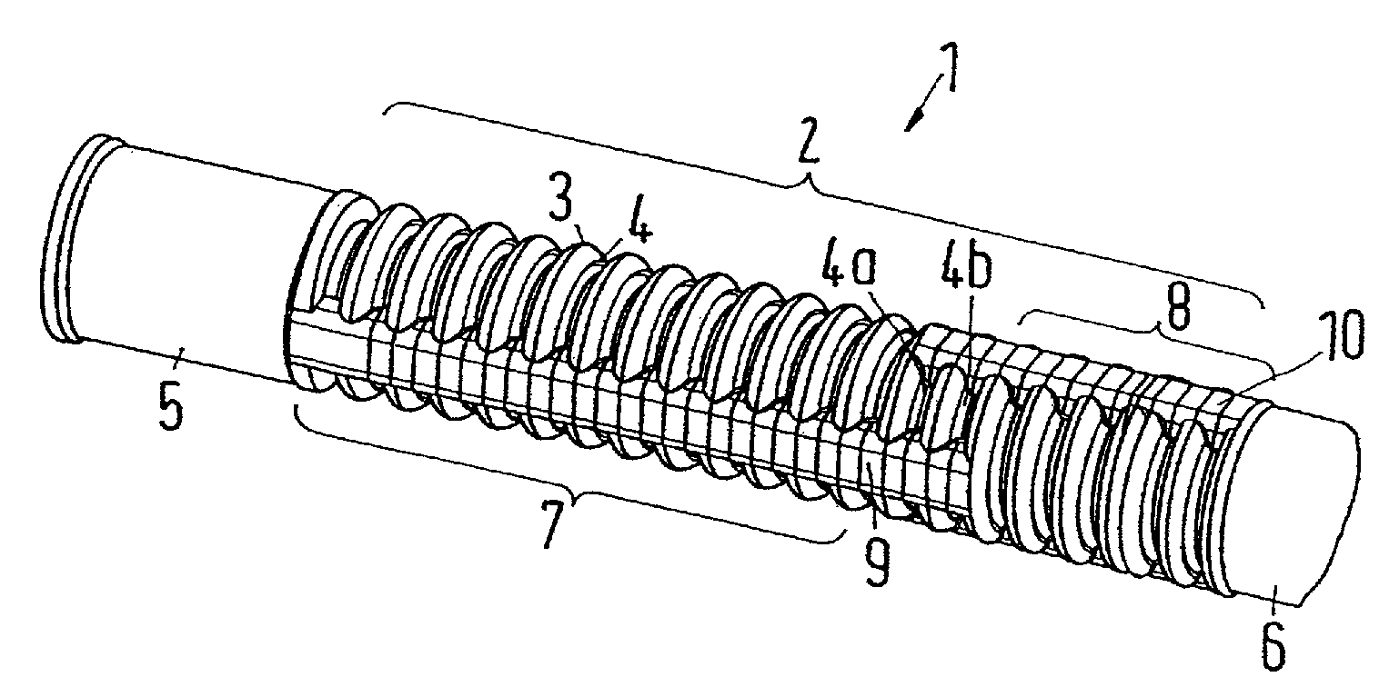
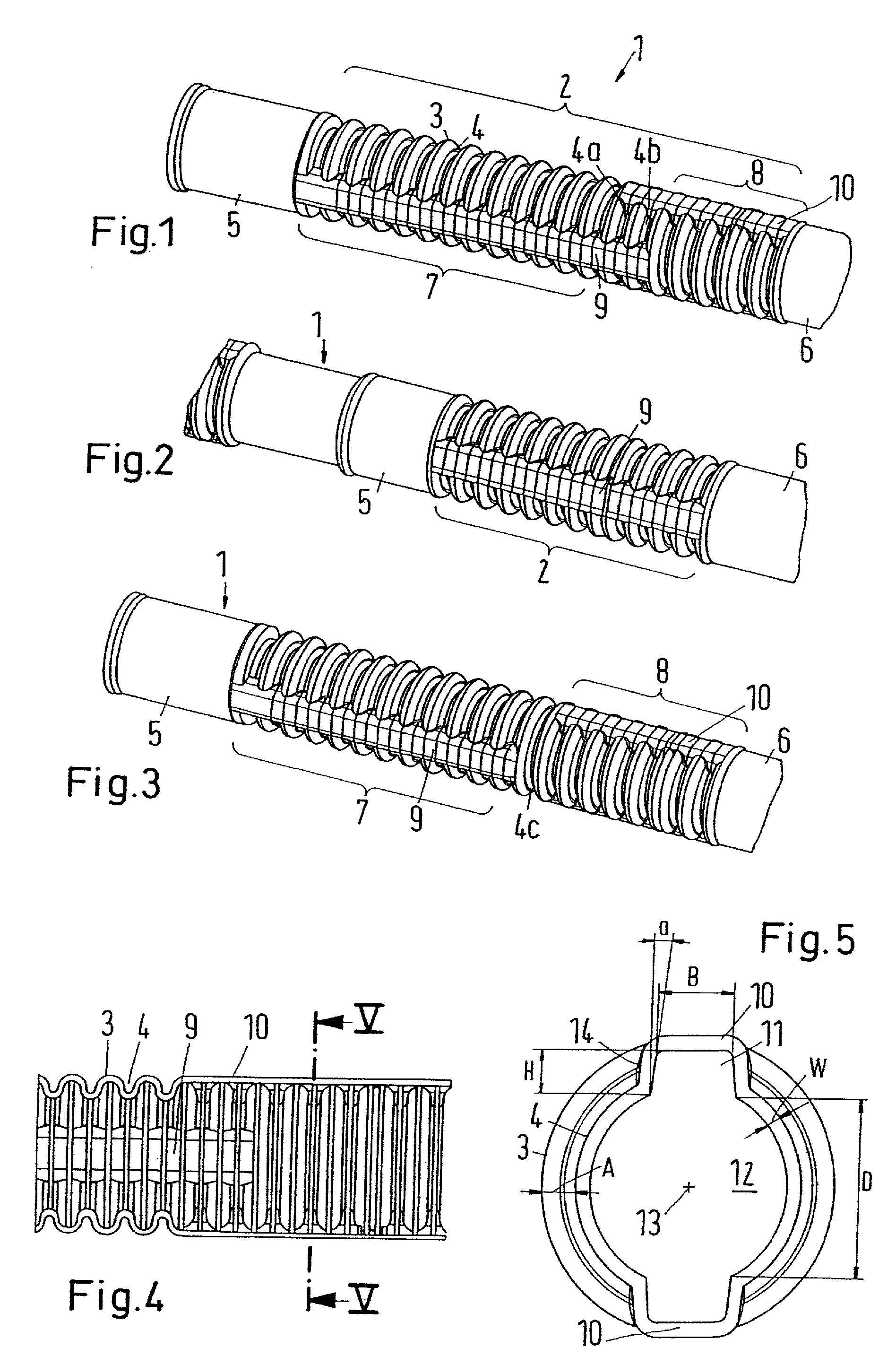
[0041]FIG. 1 shows a fluid line 1 having a corrugated section 2. The corrugated section has wave peaks 3 and wave troughs 4 arranged therebetween.

[0042]A non-corrugated section 5 adjoins the corrugated...


PUM


Abstract

A fluid line includes at least one corrugated section having wave peaks and wave troughs and at least one tie rod arranged in at least one portion of the corrugated section and being coupled to plural wave peaks. A method of making the fluid line includes forming at least one corrugated section at an end area or beginning area of a generally cylindrical section of the fluid line.

Description

CROSS-REFERENCE TO RELATED APPLICATIONS[0001]The present application claims priority under 35 U.S.C. §119 of German Patent Application No. DE 10 2008 037 740.6 filed Aug. 14, 2008, the disclosure this German priority document is expressly incorporated by reference herein in its entirety.BACKGROUND OF THE INVENTION[0002]1. Field of the Invention[0003]The invention relates to a fluid line with at least one corrugated section that has wave peaks and wave troughs. The invention also relates to method of making the fluid line includes forming at least one corrugated section at an end area or beginning area of a generally cylindrical section of the fluid line[0004]2. Discussion of Background Information[0005]A fluid line of this type is known, for example, from DE 44 32 584 C1. A line of this type can be curved in the corrugated section. As a result, a greater freedom in the line routing is achieved. On the other hand, with a fluid line of this type it is also possible to connect elements...

Claims


Application Information

Patent Timeline
Patent Type & Authority Patents(United States)
IPC IPC(8): F16L11/00
CPCF16L11/11F16L11/118
Inventor PALMERI, GAETAN
Owner NORMA GERMANY GMBH
Why Eureka
Try Eureka