Light optical angle modulation measurement apparatus and measurement method

a technology of optical angle modulation and measurement apparatus, which is applied in the direction of optical radiation measurement, measurement devices, instruments, etc., can solve the problems of difficult conversion of electromagnetic waves having such an extremely high frequency, degraded optical phase modulation waveform, and error in distance estimation, so as to accurately measure the temporal waveform of optical, the effect of complicated procedure and stabilization of the optical path length of the interferometer

Active Publication Date: 2019-08-22
NAT INST OF ADVANCED IND SCI & TECH
View PDF0 Cites 3 Cited by
  • Summary
  • Abstract
  • Description
  • Claims
  • Application Information

AI Technical Summary

Benefits of technology

[0049]In the optical angle modulation measurement apparatus of the present invention, in an optical angle modulation measurement apparatus by a delayed self-heterodyne method, a heterodyne interferometer that is fed with laser light to be measured which is optical-angle modulated by a signal generator, a light detector which that is configured to receive output light of the heterodyne interferometer to perform heterodyne detection, a phase demodulator that is configured to demodulate a phase of a beat signal output from the photodetector, and a time waveform analyzer that is configured to obtain a temporal waveform of optical angle modulation, from the phase of the beat signal are provided, so it is possible to accurately measure the temporal waveform of optical angle modulation.
[0050]In the optical angle modulation measurement method of the present invention, by using a delayed self-heterodyne method, laser light to be measured which is optical-angle modulated is input to a heterodyne interferometer, output light of the heterodyne interferometer is received and heterodyne detection of the output light is performed, by a photodetector, and a temporal waveform of optical angle modulation is obtained by demodulating a phase of the beat signal output from the photodetector, so it is possible to accurately measure the temporal waveform of optical angle modulation.
[0051]Further, in the apparatus and method of the present invention, the phase of the beat signal generated by the heterodyne interferometer is measured, so it is not affected by light intensity modulation. Therefore, the apparatus and method are applicable to the semiconductor laser light source directly modulated by injection current. Further, according to the apparatus and method of the presen...

Problems solved by technology

In distance measurement by the lidar, the fact that the optical frequency increases (up-chirp) or decreases (down-chirp) in proportion to time is used, but in a case where the chirp is nonlinear with respect to time, the beat frequency changes irregularly and produces an error in distance estimation.
Howeve...

Method used


Image

  • Light optical  angle modulation measurement apparatus and measurement method
  • Light optical  angle modulation measurement apparatus and measurement method
  • Light optical  angle modulation measurement apparatus and measurement method

Examples


first embodiment

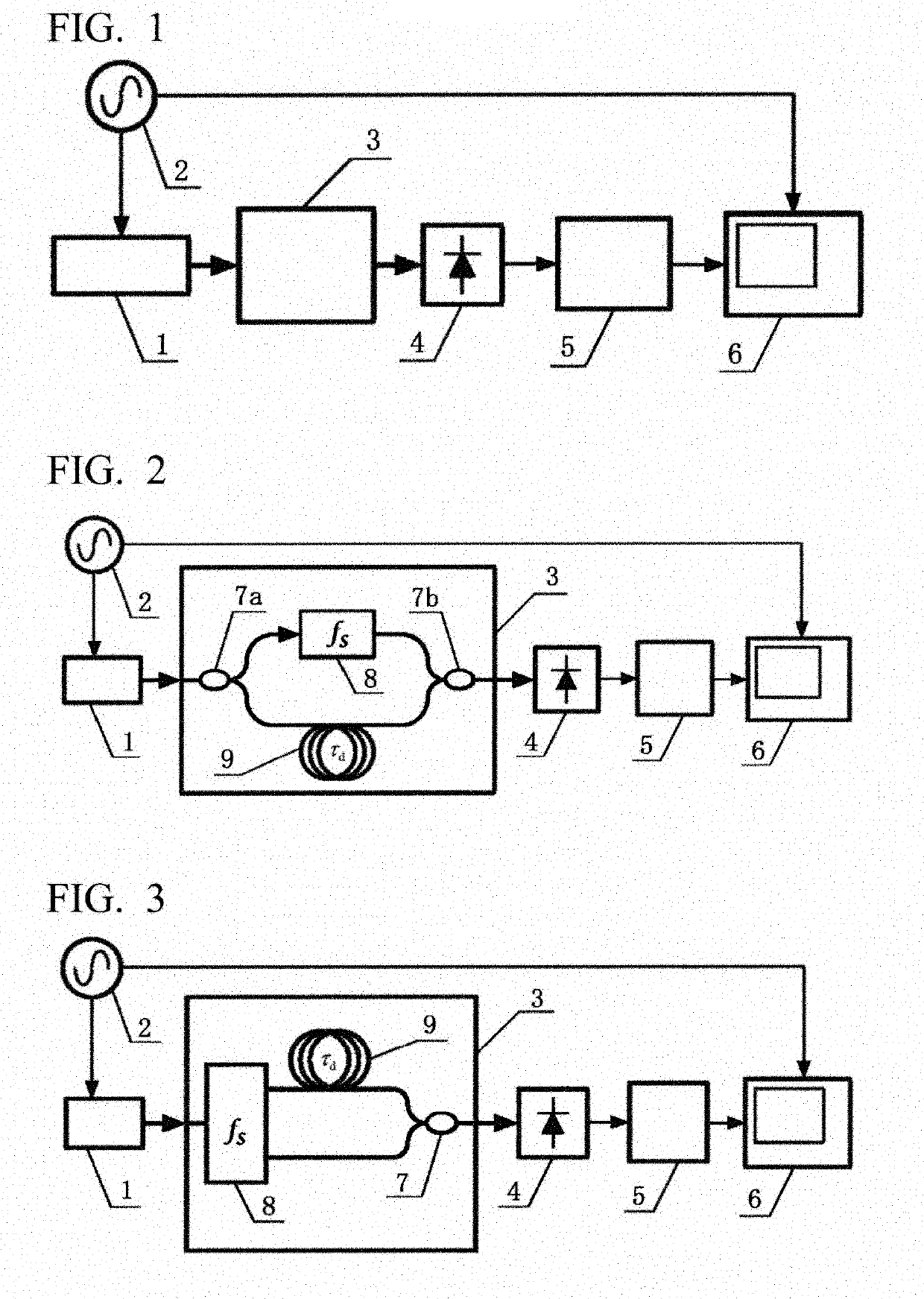
[0066]A first embodiment will be described below with reference to FIGS. 1 and 2. In the first embodiment, in an optical angle modulation measurement apparatus of FIG. 1, a Mach-Zehnder interferometer is used as the heterodyne interferometer 3. FIG. 2 is a diagram showing the first embodiment. The output light of the laser 1, which is the laser light to be measured which is optical-angle modulated by the signal generator 2, is branched into two by the optical directional coupler 7a. One is input to the optical frequency shifter 8 and the other is input to the optical delay medium 9. The light subjected to the frequency shift of fS by the optical frequency shifter 8 and the light delayed by time τd by the optical delay medium 9 are combined by the optical directional coupler 7b and output.

[0067]An acousto-optic modulator can be used as the optical frequency shifter 8. In the acousto-optic modulator, the frequency shift of the diffracted light to be output is selected as either positi...

second embodiment

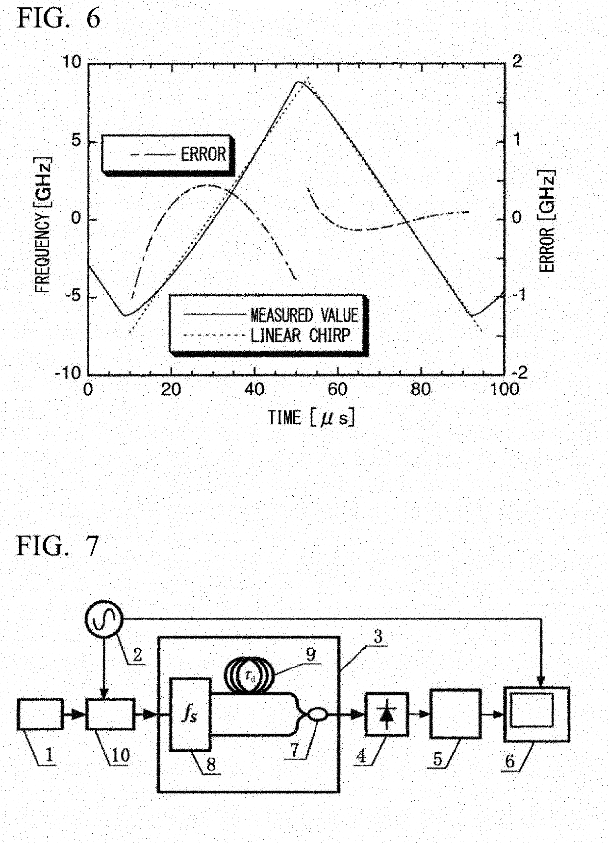
[0079]A second embodiment will be described below with reference to FIG. 1, and FIGS. 3 to 8. In the second embodiment, in an optical angle modulation measurement apparatus of FIG. 1, a Mach-Zehnder interferometer is used as the heterodyne interferometer 3. FIG. 3 is a diagram showing the second embodiment. The output light of the laser 1 which is the laser light to be measured whose optical angle is modulated by the signal generator 2 is input to the optical frequency shifter 8 of the frequency shift fS. The optical frequency shifter 8 simultaneously outputs zeroth-order diffracted light not subjected to frequency shift and first-order diffracted light subjected to frequency shift of fS. The zeroth-order diffracted light delayed by time τd by the optical delay medium 9 and the first-order diffracted light are combined and output by the optical directional coupler 7, and are received by the photodetector 4. The configuration after the photodetector 4 is the same as that of the first...


PUM


Abstract

An apparatus and a method which enable, in optical angle modulation, measurement of laser light, to measure by a delayed self-heterodyne method, accurate measurement of a temporal waveform of optical angle modulation, without any influence by light intensity modulation, without necessity of for calibration, and without necessity for stabilizing an interferometer. In an optical angle modulation measurement apparatus using a delayed self-heterodyne method, a heterodyne interferometer that is fed with laser light to be measured; a photodetector that receives output light of the heterodyne interferometer and performs heterodyne detection of the output light to output a beat signal; using a phase demodulator that is configured to demodulate a phase of a beat signal; and a temporal waveform analyzer that is configured to obtain a temporal waveform of optical angle modulation, from the phase of the beat signal. In an optical angle modulation measurement method by a delayed self-heterodyne method, laser light to be measured, which is optical-angle modulated is input to a heterodyne interferometer, heterodyne detection of the output light is performed by a photodetector, and a temporal waveform of optical angle modulation is obtained by demodulating a phase of the beat signal.

Description

TECHNICAL FIELD[0001]The present invention relates to an optical angle modulation measurement apparatus and an optical angle modulation measurement method suitable for high-accuracy measurement of optical frequency modulation or optical phase modulation of a laser light source useful for optical sensing and the like. Optical angle modulation is a generic term for the optical frequency modulation and the optical phase modulation.BACKGROUND ART[0002]Semiconductor lasers having emission wavelengths in the near infrared region are widely used not only as light sources for large-capacity optical fiber communication systems but also as various light sources for optical sensing. The intensity and frequency of the output light of the semiconductor laser can be modulated by modulating the injection current, so the semiconductor lasers are used in various high-sensitivity sensing systems in combination with heterodyne or homodyne detection. In addition, a method of phase modulation of the out...

Claims


Application Information

Patent Timeline
IPC IPC(8): G01B9/02G01J9/02G01S17/08G01S7/481
CPCG01B9/02083G01J9/02G01S17/08G01S7/481G01B9/02G01J9/04G01S17/34G01S7/4911G01S7/4915G01S7/4917
Inventor TSUCHIDA, HIDEMI
Owner NAT INST OF ADVANCED IND SCI & TECH
Why Eureka
Try Eureka