

Auto-release venturi with vacuum switch
- Summary
- Abstract
- Description
- Claims
- Application Information
AI Technical Summary
Benefits of technology
Problems solved by technology
Method used
Image

Examples
Embodiment Construction
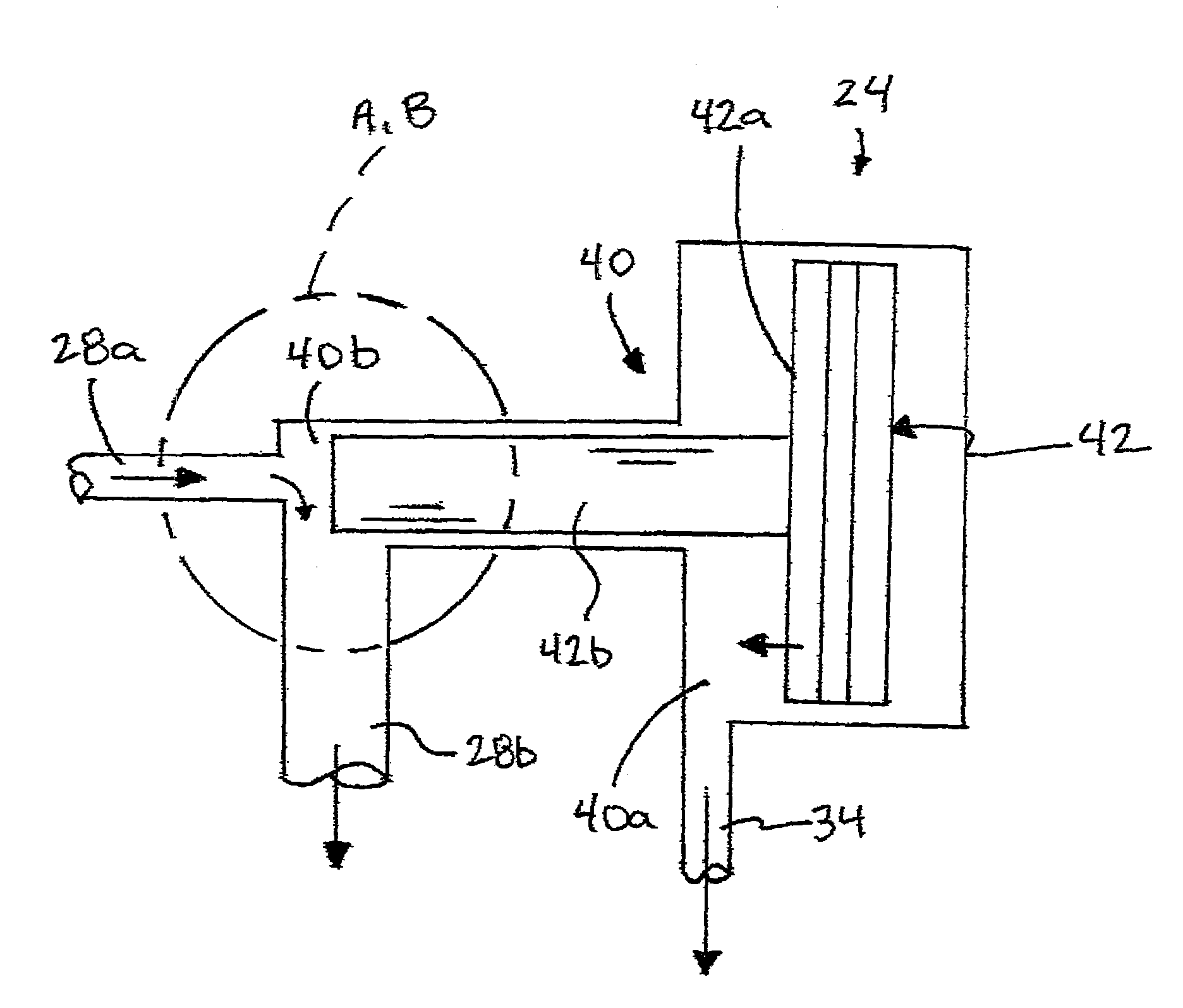
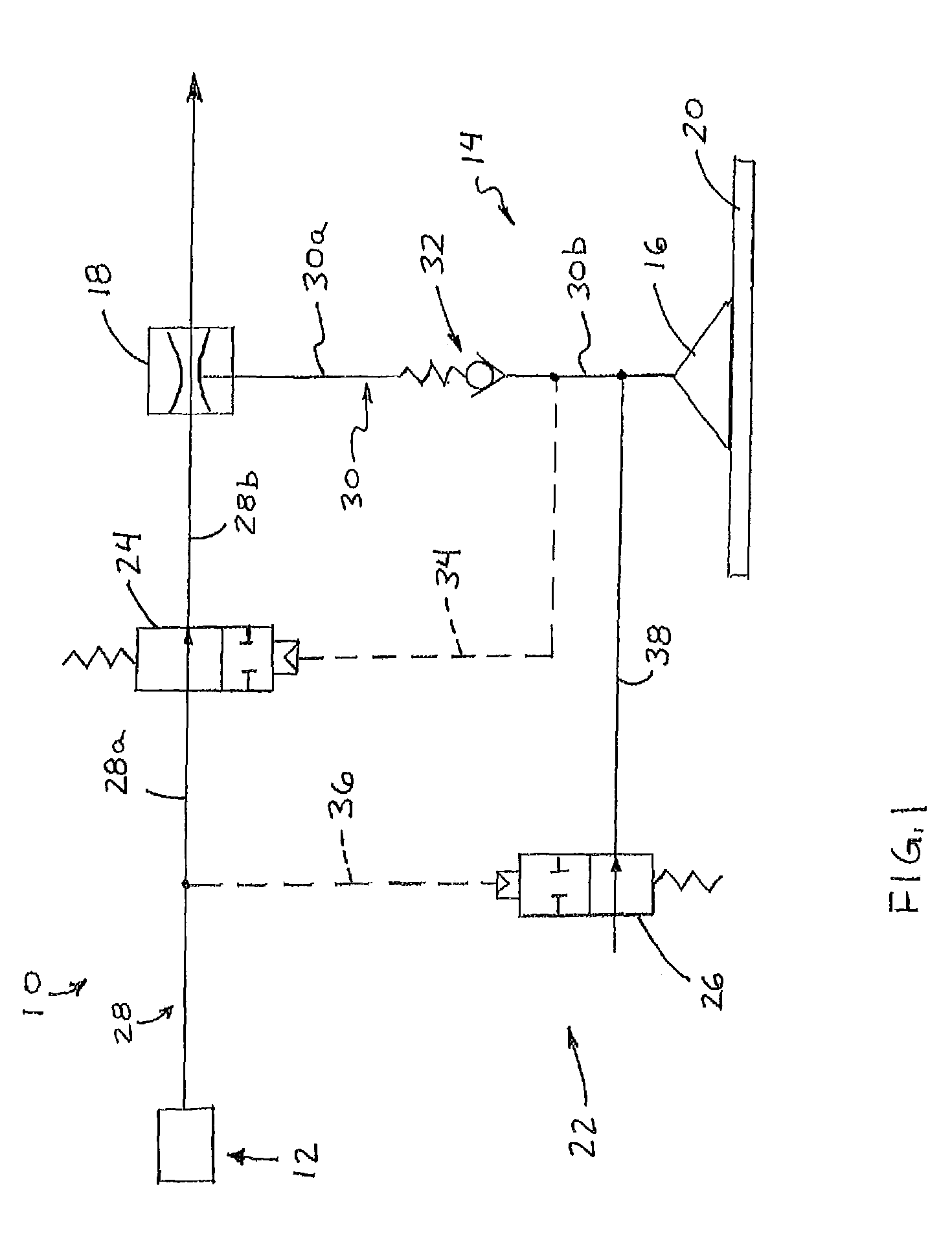
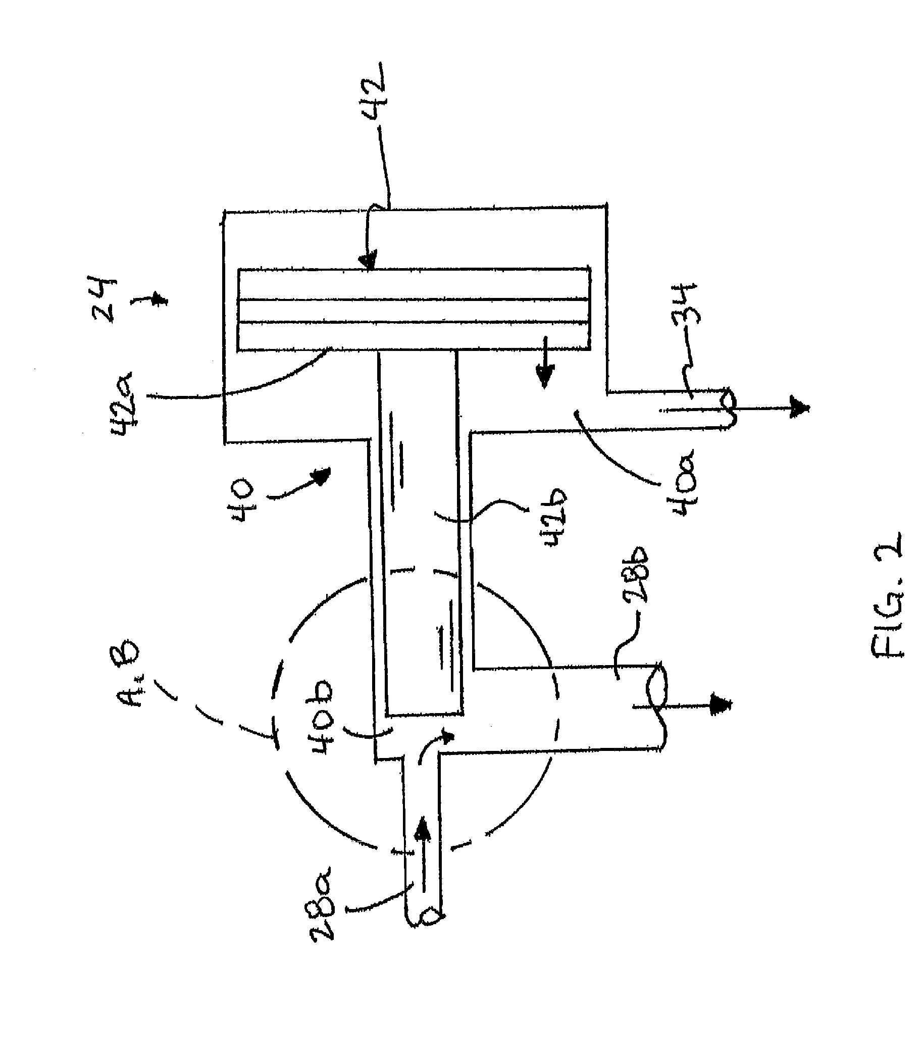
[0016]Referring now to the drawings and the illustrative embodiments depicted therein, a material handling system 10 includes a pressurized air supply or source 12 and a vacuum cup assembly 14, which includes a vacuum cup 16 and a venturi device 18 that is configured to create a vacuum or partial vacuum within the vacuum cup 16 when the vacuum cup is engaged with a surface of an object 20 and when the pressurized air supply is activated to force or blow pressurized air through the venturi device (FIG. 1). The vacuum cup assembly 14 is mountable to a support assembly (not shown) of a material handling system, which is operable to move the support and vacuum cup assembly (or multiple vacuum cup assemblies or suction cups) into engagement with an object, where the vacuum cup may engage and seal to the object, and is operable to pick up and move the object to a targeted destination, whereby the object may be released from the vacuum cup or cups. The material handling system includes a p...
PUM
 Abstract
Description
Claims
Application Information