High performance planing hull provided with a trim tab system

a trim tab and high-performance technology, applied in the direction of waterborne vessels, floating buildings, vessel construction, etc., can solve the problems of frequent maintenance, particularly hazardous mechanical parts, and the installation of a large number of hulls, so as to reduce the minimum speed, increase the visibility of the surrounding environment for users, and improve the effect of performan

Active Publication Date: 2012-01-24
FB DESIGN
View PDF11 Cites 33 Cited by
  • Summary
  • Abstract
  • Description
  • Claims
  • Application Information

AI Technical Summary

Benefits of technology

[0015]The object of the present invention is to overcome the drawbacks of prior art and in particular to adjust the trim of the planing hull in operating conditions in which the acting hydrodynamic thrust has null or negligible intensity, while maintaining a position with the centre of gravity positioned far back to ensure high performance of the hull.
[0016]Another object of the present invention is to improve visibility from the bow of the hull obtaining a more “horizontal” trim in acceleration conditions before reaching a stable planing trim.
[0017]A further object of the present invention is to reduce the minimum speed at which the hull adopts a planing trim and the time required to reach this, above all in particularly heavy hulls or those designed for fast passenger transport or for military and patrol purposes.

Problems solved by technology

The actuating means of the trim adjusting systems formed by movable surfaces have the considerable drawback of being installed in areas subject to high levels of humidity and salinity, if the hull is used in sea water.
These phenomena are particularly hazardous for mechanical parts, which require frequent maintenance.
The recent increase in the use of high performance planing hulls, in terms of speed and useful carrying load has led to further problems concerning the trim of the boat in some conditions of use and in particular during acceleration before reaching a stable planing trim.
Although allowing high performance in terms of speed, this characteristic leads to “bow up” trim during acceleration, i.e. the bow of the boat is lifted high above the surface of the water, with consequent visibility problems.
Moreover, in standing start, manoeuvring and / or low speed operating conditions the hydrodynamic force acting on the hull is null or of negligible intensity.

Method used


Image

  • High performance planing hull provided with a trim tab system
  • High performance planing hull provided with a trim tab system
  • High performance planing hull provided with a trim tab system

Examples


Embodiment Construction

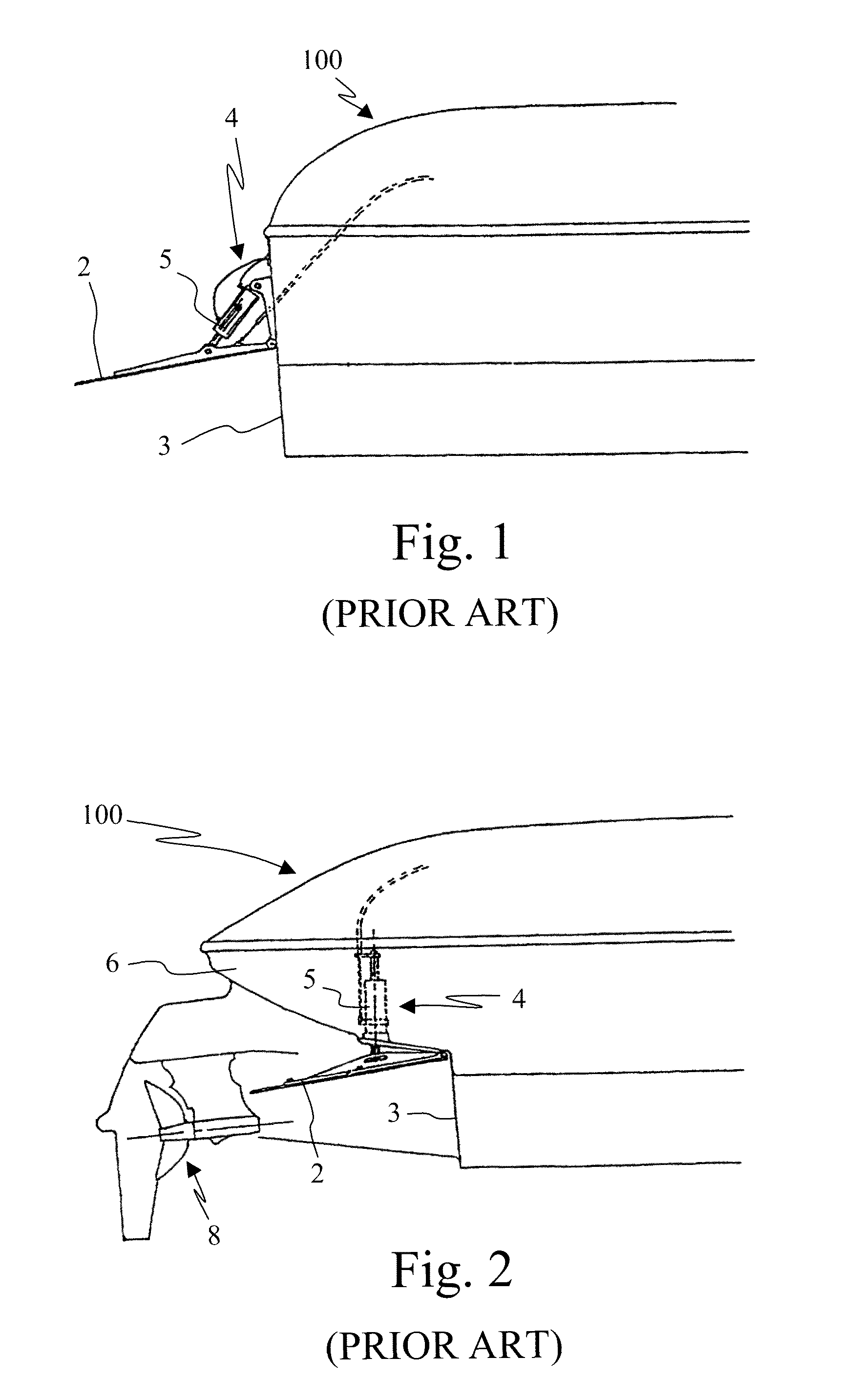
[0035]FIG. 1 shows the stern of a planing hull 100 according to the prior art, provided with a pair of movable trim tabs of conventional type, positioned symmetrically at the sides of the propulsion system.

[0036]In order to simplify the view, only one movable trim tab is shown in FIG. 1 and the propulsion system of the boat has been omitted. The movable surface 2 of the trim tab is constrained to the transom 3 of the hull 100. The actuating means 4 for deflection of the movable surface 2 comprise a pneumatic or hydraulic actuator 5 and allow the user of the boat to adjust the trim of the hull 100 with respect to the surface of the water.

[0037]In this type of installation the trim tabs, and in particular the corresponding actuating means 4, are fixed to the outside of the hull 100, with consequent problems deriving from exposure of the mechanical parts to water and atmospheric agents.

[0038]To overcome these problems it is known in the art to install the actuating means of the movable...


PUM


Abstract

A high performance planing hull, designed in particular for boats with drives of fixed or non-steerable type. The hull comprises an additional volume, which is integrated in the immersed part of the stern of the hull. The additional volume extends substantially in longitudinal direction and is symmetrical with respect to the longitudinal plane of symmetry of the hull.

Description

BACKGROUND OF THE INVENTION[0001]The present invention relates to a high performance planing hull, in terms of speed and carrying load, provided with a trim tab system. The term “trim tab” is intended as a surface and / or volume positioned at the immersed part of the stern, capable of adjusting the hull trim with respect to the free surface of the water in specific operating conditions.[0002]The prior art comprises planing hulls provided with movable surfaces used to adjust the trim of the boat, known as trim tabs or flaps. When these surfaces are struck by a water flow they generate a hydrodynamic force, which is multiplied by the existing arm between the point in which force is applied and the centre of gravity of the hull to determine a couple that modifies the trim of the boat with respect to the surface of the water.[0003]The couple generated determines rotation of the hull about the pitch axis of the boat.[0004]The surface of the trim tab can be provided with actuating means wh...

Claims


Application Information

Patent Timeline
Patent Type & Authority Patents(United States)
IPC IPC(8): B63B1/22
CPCB63B39/061
Inventor BUZZI, FABIO
Owner FB DESIGN
Why Eureka
Try Eureka