Float valve apparatus

a float valve and valve body technology, applied in the direction of valve operating means/release devices, liquid handling, packaging goods types, etc., can solve the problems of insufficient control of collision between the float valve and the housing, the outside diameter of the elastic buffer, and the inability to set the load with high accuracy, so as to achieve smooth movement up and down

Inactive Publication Date: 2012-01-24
PIOLAX CO LTD
View PDF12 Cites 16 Cited by
  • Summary
  • Abstract
  • Description
  • Claims
  • Application Information

AI Technical Summary

Benefits of technology

[0014]According to such configuration, for example, when liquid such as the fuel of a car flows into the housing and the liquid surface of the liquid rises up to a given height or more, the float valve is moved upward to close the opening formed in the partition wall, thereby being able to prevent the liquid from flowing into the upper space through the opening. For example, as applied to the fill-up control valve of the fuel tank of the car or to the cut-off valve thereof, the fill-up control in the fuel supply operation can be carried out and the leakage of the fuel to the outside can be prevented.
[0028]According to such configuration, the support spring is inserted into the support spring storage recess formed to have a depth larger than the free length of the support spring and also the projection provided on the bottom surface of the housing is inserted into the support spring storage recess. This can surely prevent mutual interference between the support spring and upward urging spring disposed outside the support spring. Since, when the float valve rises and falls, the projection is to be slidingly contacted with the inner periphery of the support spring storage recess, the rising and falling operation of the float valve is guided such that the float valve is prevented against inclination and de-centering, whereby the float valve can be moved up and down smoothly.

Problems solved by technology

However, in such float valve apparatus, when the car runs along a rough road, the float valve can collide with the bottom surface of a housing to generate a strange sound.
However, in JP-UM-H06-040552-A, since the elastic buffer for supporting the lower surface of the float valve is disposed outside a spring for urging the float valve upwardly, the outside diameter of the elastic buffer is large, which makes it difficult to set the load, free length and the like of the elastic buffer with high accuracy.
Also, since, when the float valve is moved down in an inclined manner, the load concentrates on the local portion of the large outside diameter elastic buffer, there is raised a possibility that the collision of the float valve with the housing cannot be controlled sufficiently.
In JP-H07-035255-A, when the valve housing is formed of hard resin from the viewpoint of heat resistance, the elasticity of the cantilever valve body support portion is poor, which lowers the hitting sound reduction effect when the valve housing is collided with the float valve.

Method used


Image

  • Float valve apparatus
  • Float valve apparatus
  • Float valve apparatus

Examples


Embodiment Construction

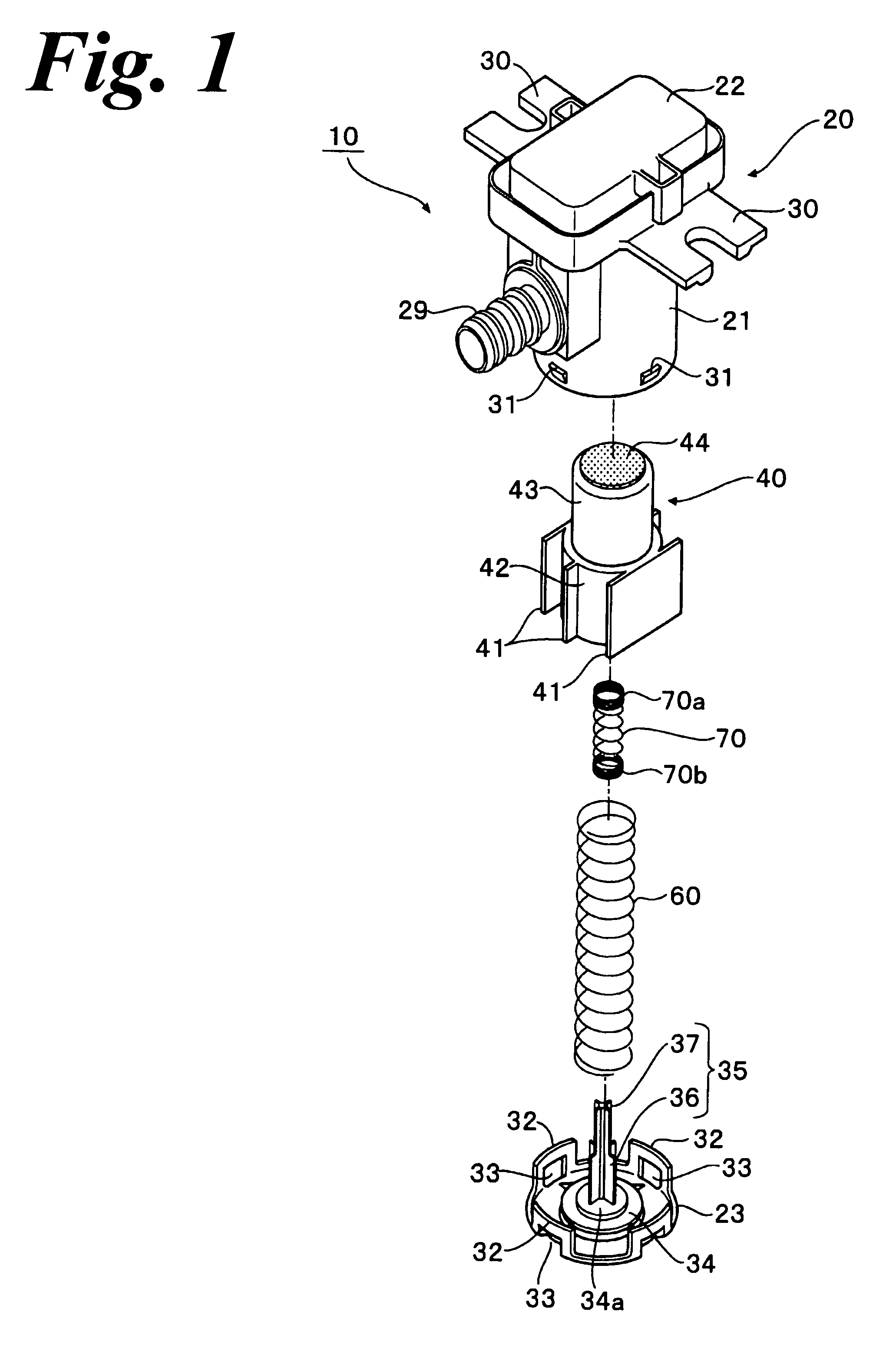
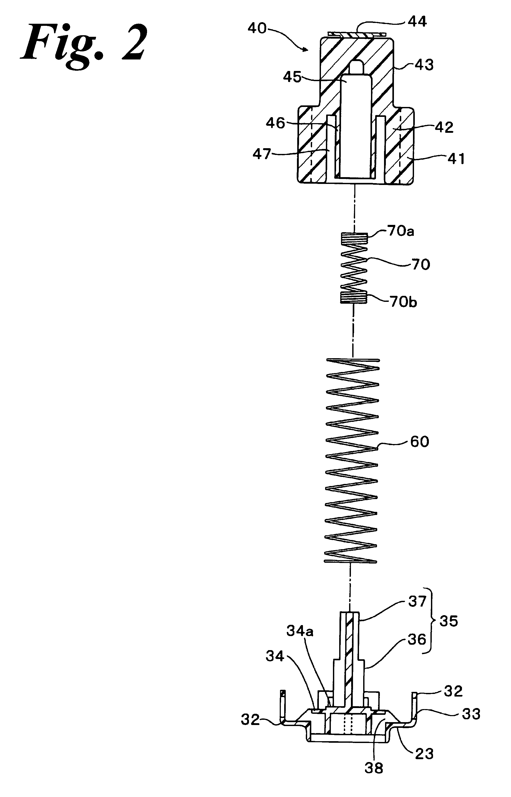
[0037]Next, description will be given below of an embodiment of a float valve apparatus according to the invention with reference to FIGS. 1 to 5.

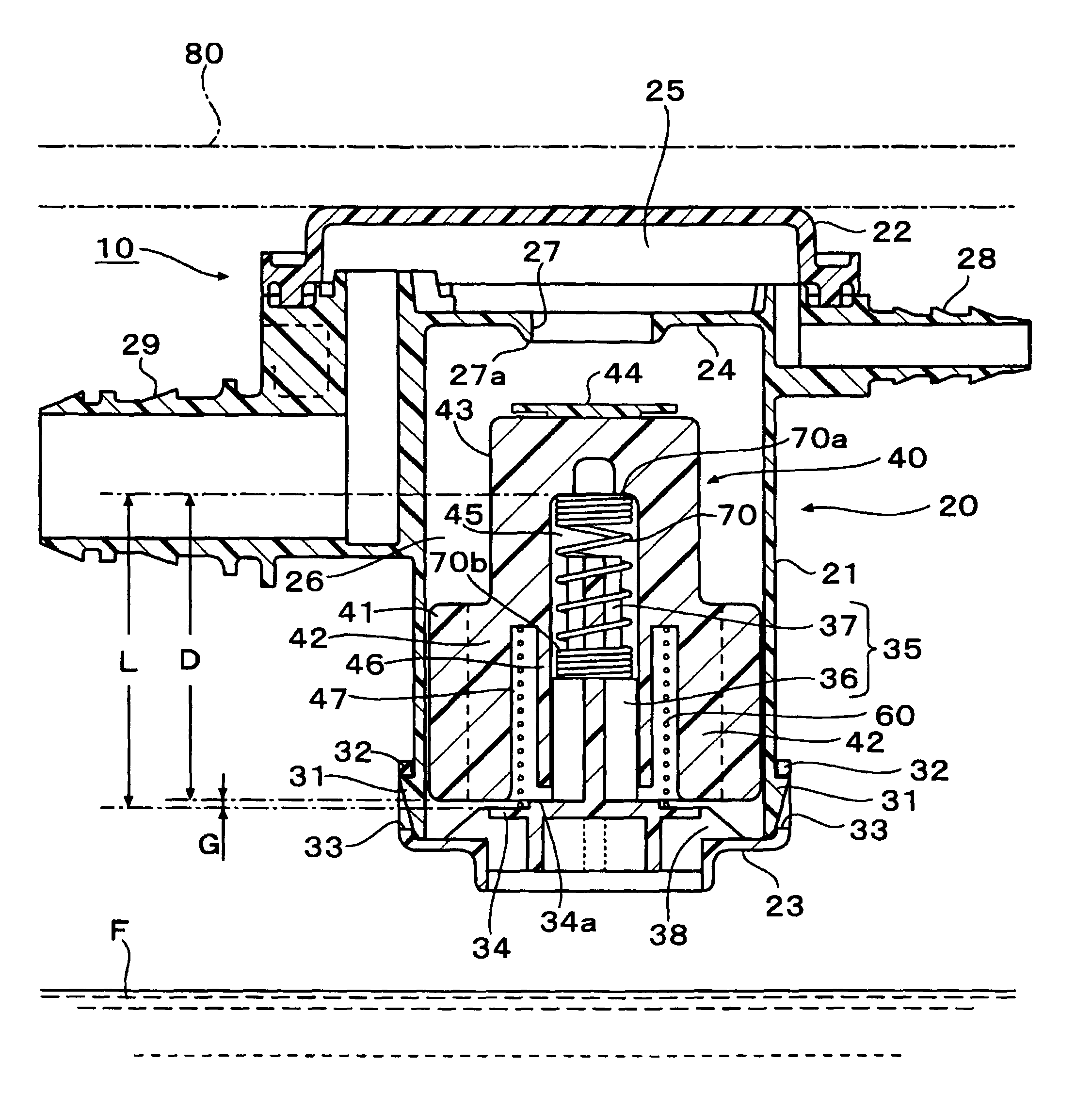
[0038]As shown in FIG. 1, this float valve apparatus 10 includes a housing 20, a float valve 40, an upward urging spring 60 and a support spring 70.

[0039]Referring to FIG. 3 together with FIG. 1, the housing 20 includes a housing main body 21, an upper cap 22 and a lower cap 23. In the upper portion of the housing main body 21, a partition wall 24 is provided to divide the inside portion of the housing 20 into an upper space 25 and a lower space 26.

[0040]An opening 27 is formed in the partition wall 24, and the lower edge portion of the opening 27 forms a valve seat 27a. A connecting pipe 28 and a connecting pipe 29 (respectively functioning as ventilation pipes) are formed on the side walls of the housing main body 21. The base end sides of the connecting pipes 28 and 29 are respectively opened in the upper space 25 that is closed by the ...


PUM

PropertyMeasurementUnit
depthaaaaaaaaaa
lengthaaaaaaaaaa
diameteraaaaaaaaaa

Abstract

According to an aspect of the present invention, there is provided a float valve apparatus including: a housing including: a partition wall dividing an internal space into lower and upper spaces and having an opening therein; a ventilation pipe communicating the upper space with an outside; a valve seat formed at the opening; and a communication hole communicating the lower space with the outside; a float that is valve vertically slidably movable in the lower space and that upwardly floats in accordance with liquid flowing thereinto to open and close the opening; an upward urging spring urging the float valve from the housing toward the opening; and a support spring disposed inside the upward urging spring to support the float valve to not contact with a bottom surface of the housing.

Description

CROSS-REFERENCE TO RELATED APPLICATIONS[0001]This application claims priority from Japanese Patent Application No. 2008-133449 filed on May 21, 2008, and from Japanese Patent Application No. 2008-175732 filed on Jul. 4, 2008, the entire contents of which are incorporated herein by reference.BACKGROUND OF THE INVENTION[0002]1. Field of the Invention[0003]An aspect of the present invention relates to a float valve apparatus suitable for use as a fuel fill-up control valve, a cut valve or a similar valve to be mounted on, for example, the fuel tank of a car.[0004]2. Description of the Related Art[0005]On the fuel tank of a car, there is mounted a fuel fill-up control valve which, when fuel is supplied up to the fill-up position of the fuel tank, closes the opening of the fuel tank communicating with the outside to stop the supply of the fuel.[0006]Also, there is provided a cut valve which not only releases fuel steam to a canister but also, when the car jolts heavily while running or t...

Claims


Application Information

Patent Timeline
Patent Type & Authority Patents(United States)
IPC IPC(8): B65B1/30
CPCF16K31/22Y10T137/3099Y10T137/86324
Inventor HIRATA, NOBUHIRO
Owner PIOLAX CO LTD
Why Eureka
Try Eureka