Pivoting connector assembly for connecting two members

a connector and two-member technology, applied in the field of connectors, can solve the problems of difficult alignment with other frame members, two frame members not being flush against one another, etc., and achieve the effect of maximum flexibility

Active Publication Date: 2012-01-24
BOSCH REXROTH AG +1
View PDF32 Cites 68 Cited by
  • Summary
  • Abstract
  • Description
  • Claims
  • Application Information

AI Technical Summary

Benefits of technology

[0004]The present invention relates to connectors and provides a connector that is internal to the frame members while still allowing the user to have maximum flexibility in positioning the two frame members. The present invention also provides a tight connection between two frame members, substantially locking the two frame members against any relative movement, including translational movement as well as rotational movement.
[0005]One embodiment of the present invention is directed to a connector configured to interconnect two frame members. The connector includes a connector member including a body and a fulcrum. The body has a first end and a second end spaced from the first end and is configured to be received within a channel in a first one of the two frame members. The fulcrum is coupled to the body between the first end and the second end and provides a pivot point about which the body can pivot within the channel of the first frame member to selectively lock the two frame members against relative movement.

Problems solved by technology

However, the external features do not allow two frame members to be located flush against one another.
The external features introduce additional spaces between frame members and make alignment with other frame members difficult if other connectors are used which do not contain external features.

Method used


Image

  • Pivoting connector assembly for connecting two members
  • Pivoting connector assembly for connecting two members
  • Pivoting connector assembly for connecting two members

Examples


first embodiment

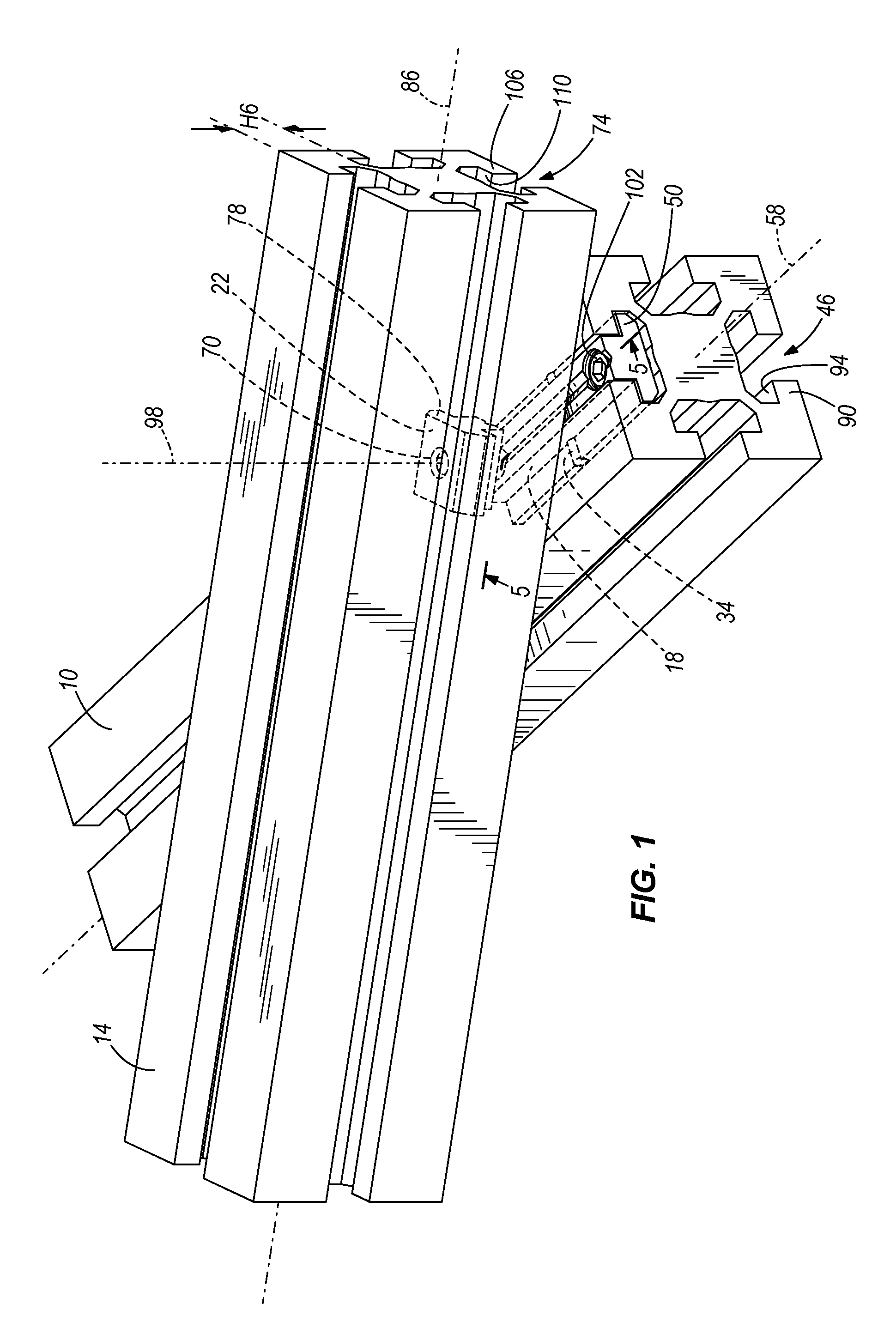
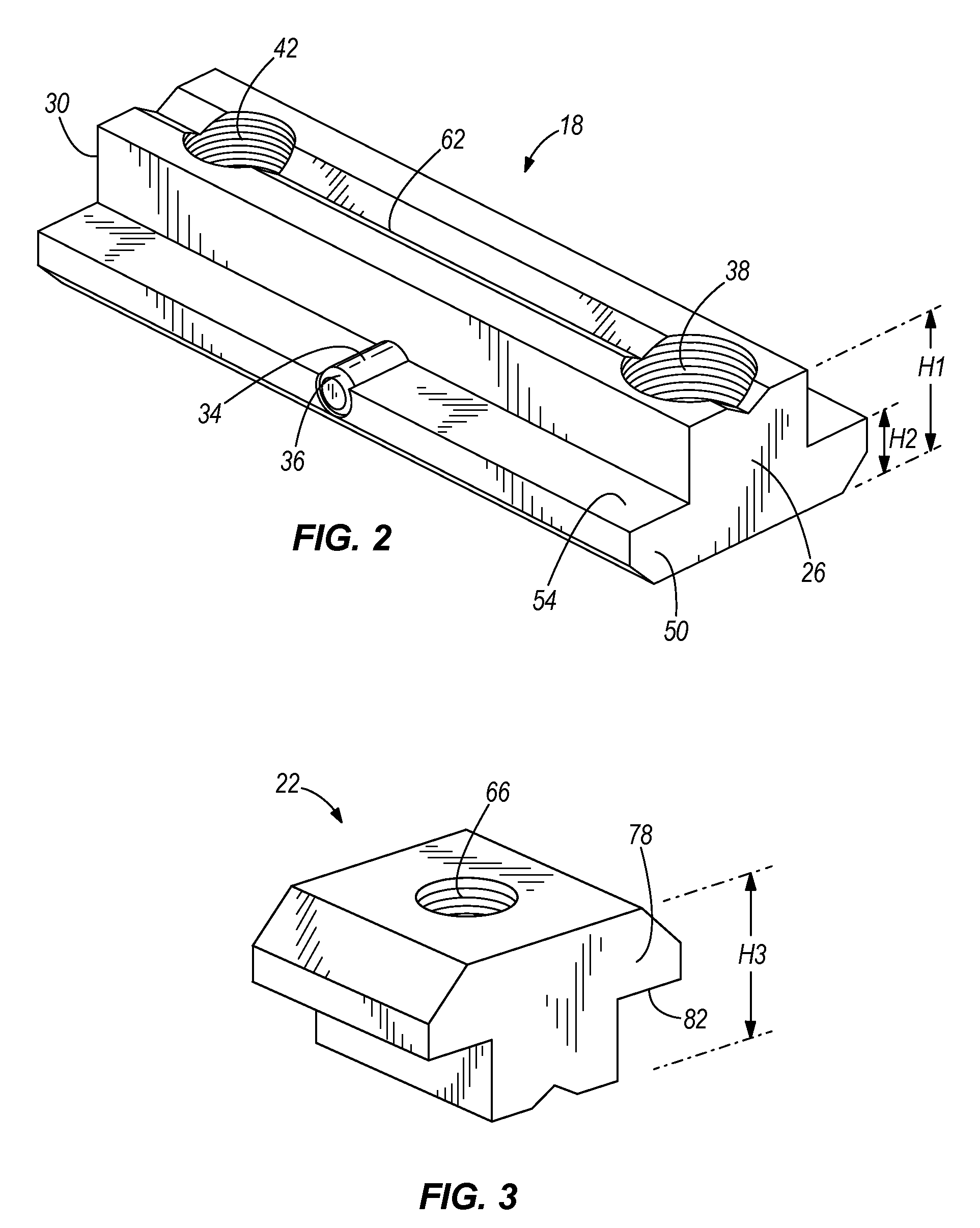
[0032]Before explaining the operation of the present invention in detail, it is important to note the relationship between the connector member 18 and the channel 46 of the first frame member 10. With reference to FIG. 2, the connector member 18 has a generally T-shaped cross-section with an overall height H1 of the body and a height H2 of the flange 50. With reference to FIG. 4, the channel 46 in the first frame member 10 has an overall height H4 and a height H5 of the receiving portion defined between the interior surface 94 and the bottom of the channel 46. The proportions of the connector member 18 are formed such that the connector member 18 may be inserted into the channel 46 of the first frame member 10. The height H1 of the connector member 18 is less than the height H4 of the channel 46 such that no portion of the connector member 18 will extend outside the channel 46 of the first frame member 10 in a direction perpendicular to the longitudinal axis 58 of the first frame me...

second embodiment

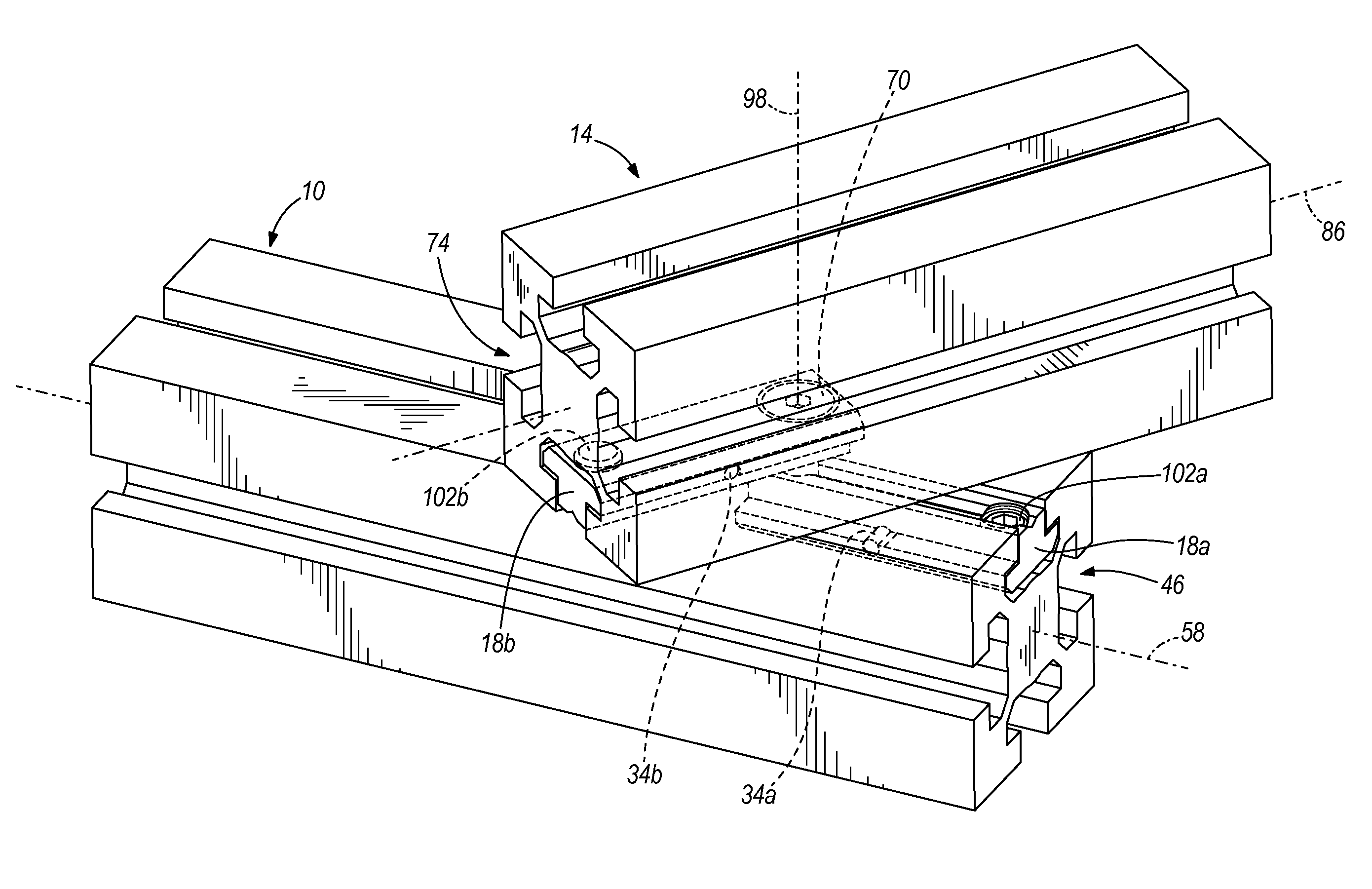
[0050]Readjustment of the frame members 10, 14 in the second embodiment may be achieved by loosening and retightening of at least one of the set screws 102a, 102b. As previously stated, the user is not required to maintain access to both of the set screws 102a, 102b. One or the other may remain inaccessible in a desired configuration, and the integrity of the connection is not compromised. The strength of the forces produced to substantially lock the frame members 10, 14 against relative movement does not depend upon which set screw 102a, 102b is tightened.

[0051]The second embodiment of the present invention provides one example of how a connector embodying the present invention may provide additional flexibility over the first embodiment, shown in FIG. 1. For example, the user may choose to tighten one set screw 102a until it abuts the first frame member 10. Then, the user may make final adjustments to the orientation of the two frame members 10, 14 before tightening the other set ...


PUM

PropertyMeasurementUnit
of rotationaaaaaaaaaa
shapeaaaaaaaaaa
cross-sectional shapeaaaaaaaaaa

Abstract

A connector is configured to connect two frame members. The connector includes a body with a first end and a second end spaced from the first end. A fulcrum is coupled to the body between the first end and the second end. The body is configured to be received in a channel of a frame member and pivots about the fulcrum inside the channel between a first pivot position in which the frame members are free to move relative to one another and a second pivot position in which the frame members are locked against relative movement.

Description

FIELD OF THE INVENTION[0001]The present invention relates to connectors, and more particularly to connectors for use in connecting two frame members.BACKGROUND OF THE INVENTION[0002]It is known to connect frame members with connectors. Many connectors exist in the prior art that can be used to quickly and efficiently assemble and disassemble frame members. In particular, many connectors exist specifically for joining profiled bars or frame members with peripheral channels formed therein. The connectors of the prior art couple two frame members together by inserting the connector pieces in the channels of the profiles and using screws or other fasteners to hold the connector pieces together. Generally, each connector in the prior art allows the user to connect two frame members in one particular configuration. For example, one connector may provide an end-to-end connection while another connector may provide a perpendicular connection. The location of the connectors is generally fixe...

Claims


Application Information

Patent Timeline
Patent Type & Authority Patents(United States)
IPC IPC(8): F16B9/00
CPCF16B37/045Y10T29/49826Y10T403/4677Y10T403/7123Y10T403/4674F16B2200/40
Inventor BLUM, CARL STEWART
Owner BOSCH REXROTH AG
Why Eureka
Try Eureka