Aerodynamic vibration power-generation device

a technology of electric generators and vibrations, applied in the direction of electric generator control, machines/engines, generators/motors, etc., can solve the problems of piezoelectric transducers embedded in piezoelectric transducers deformation and vibration

Active Publication Date: 2012-01-24
TSOU KUEI SHENG
View PDF10 Cites 31 Cited by
  • Summary
  • Abstract
  • Description
  • Claims
  • Application Information

AI Technical Summary

Benefits of technology

[0005]The primary object of the present invention is to provide an aerodynamic vibration power-generation device, having at least a piezoelectric transducer embedded inside a blade. The blade is an aerodynamic vibration element that has the capability of airflow spoiling and fluttering. When the airflow passes along the surfaces of the blade, the difference between the air speeds on both sides of the blade will generate a pressure difference on the surfaces of blade, according to Bernoulli's Principle, and the pressure difference will cause the blade to deform and vibrate. The deformation and the vibration of the blade will also cause the embedded piezoelectric transducer to deform and vibrate. The vibration of the piezoelectric material will have the Piezoelectric Effect to generate electric charges. Because the wind speed is constantly changing, the airflow speeds and the pressure difference on the surfaces of the blade are also continuously changing accordingly. The continuously changing pressure difference on the surfaces of blade will sustain the blade for continuous vibration so that the embedded piezoelectric transducer continues to oscillate to generate charges.

Problems solved by technology

The deformation and the vibration of the blade will also cause the embedded piezoelectric transducer to deform and vibrate.

Method used


Image

  • Aerodynamic vibration power-generation device
  • Aerodynamic vibration power-generation device
  • Aerodynamic vibration power-generation device

Examples


Embodiment Construction

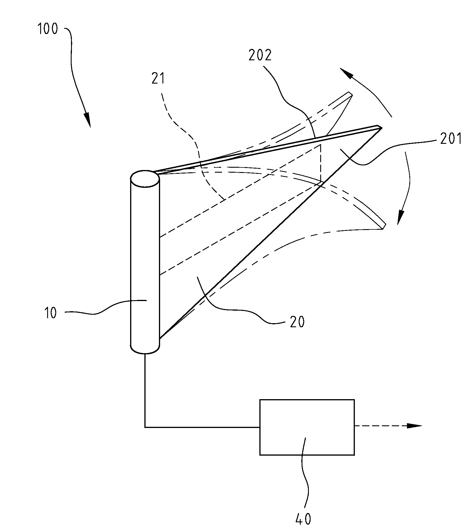
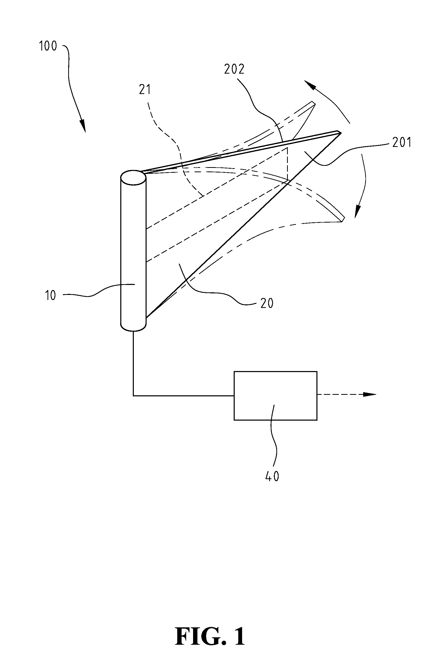
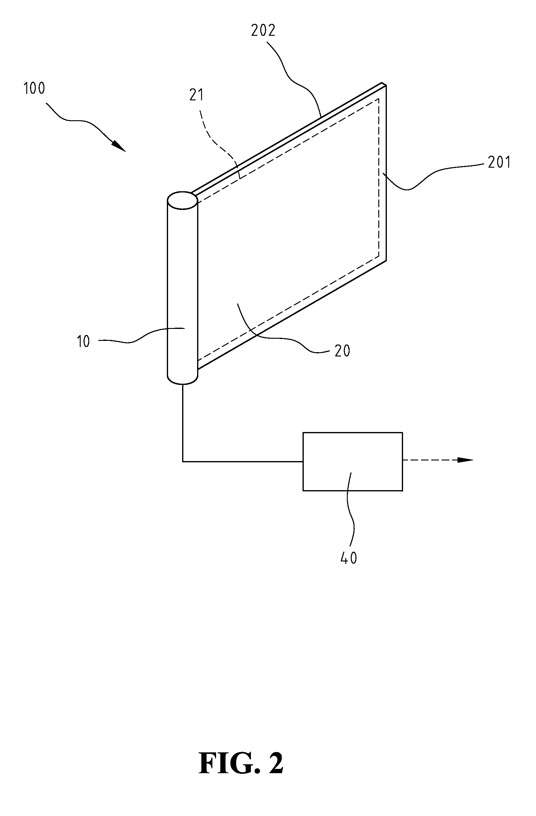
[0015]FIG. 1 shows a schematic view of the first embodiment of the present invention. As shown in FIG. 1, an aerodynamic vibration power-generation device 100 of the present invention includes at least a brace 10, and at least a blade 20. One side of blade 20 is attached to brace 10. Blade 20 is a thin and flexible aerodynamic vibration element with at least an embedded piezoelectric transducer 21. Piezoelectric transducer 21 is made of piezoelectric material and electrodes, and is deflectable and flexible. When piezoelectric transducer 21 is vibrated because of the vibration of blade 20, piezoelectric transducer 21 will transform the mechanical energy of vibrating blade 20 into electrical energy and output electric current. Piezoelectric transducer 21 also has related circuitry to connect with a load unit 40. When the present invention is operated stand-alone, the first stage of load unit 40 can be an impedance load, a converter, a battery charging system with battery, a regulator,...


PUM


Abstract

An aerodynamic vibration power-generation device is provided, including at least a brace, and at least a blade. The blade is attached to the brace at least with one side. The blade is an aerodynamic vibration element, with at least an embedded piezoelectric transducer. The piezoelectric transducer embedded in the blade includes related circuitry for electrically connecting to a load unit. When the airflow passes along the surfaces of the blade, the difference between the air speeds on both sides of the blade will generate a pressure difference on the surfaces of the blade, according to Bernoulli's Principle, and the pressure difference will cause the blade to deform and vibrate. The fluttering and the oscillation of the blade caused by the continuously changing airflow speeds will cause the embedded piezoelectric transducer to generate electricity.

Description

FIELD OF THE INVENTION[0001]The present invention generally relates to an electricity-generating device, and more specifically to a device having a piezoelectric transducer embedded inside a blade, the piezoelectric transducer generating electricity when the blade vibrating because of the continuously changing pressure difference on the surfaces of blade caused by the continuously changing airflow speed difference on the surfaces of the blade.BACKGROUND OF THE INVENTION[0002]As the alternative energy gains popularity, the use of wind for generating electricity also attracts attention. The wind-based electricity-generation is to use the windmill to transform the wind energy into the rotational dynamics, and then use a generator module to transform the mechanical energy into electrical energy. This type of generator has a better capacity. However, the disadvantages are the low efficiency, large size, complex structure and high manufacturing cost.[0003]Piezoelectric material, such as L...

Claims


Application Information

Patent Timeline
Patent Type & Authority Patents(United States)
IPC IPC(8): F03B13/00
CPCF03D5/00F03D5/06H02N2/185F05B2220/709F05B2260/407Y02E10/70Y02E10/725Y02E10/72
Inventor TSOU, KUEI-SHENG
Owner TSOU KUEI SHENG
Why Eureka
Try Eureka