Display system and driving method thereof

a technology of display system and driving method, which is applied in the direction of static indicating device, cathode-ray tube indicator, instruments, etc., can solve the problems of irritating the user's vision, damage to the night-vision device, and the brightness of the descent is too low for the user to view the liquid crystal display directly by eyes, so as to achieve low luminance and low color level

Active Publication Date: 2012-01-24
GETAC TECH CORP
View PDF26 Cites 1 Cited by
  • Summary
  • Abstract
  • Description
  • Claims
  • Application Information

AI Technical Summary

Benefits of technology

[0007]To solve the aforesaid problems of the prior art, the present invention provides a display system and driving thereof that is capable of outputting low luminance or low color level of certain color light (such as red light), especially by descending the color level of red signal. The display system includes a liquid crystal display and an image processing device; wherein the image processing device outputs red / green / blue signals to the liquid crystal display to display images thereon.
[0008]The image processing device descends the color level of the red signal by using a control chip to control a Gamma value of the color level of the red signal. The Gamma value of the color level of the red signal output from the display chip may be modified by software, or modified by employing a color management chip in the signal transmission tunnel. No matter the color management chip is originally equipped for managing the red, green or blue signal, the color management chip will still be able to modify the Gamma value of the color level of the red signal. Such implementation will allow the user to view the display system under special situation. For example, when viewing the display system through a night-vision device, no oversaturation problem will occur on the night-vision device. In a practical implementation, the Gamma value of the color level of the red signal may even be descended to 0.

Problems solved by technology

Yet the descended brightness is too low for the user to view the liquid crystal display by eyes directly.
Such oversaturation causes damage of the night-vision device and over irritates the user's vision; it makes the user uncomfortable.
Yet currently the liquid crystal display is not designed for using under an ultra low luminance.
If the driving current of the liquid crystal display is lower than the minimum driving current limitation, flickers of the LED will occur and cause displaying instability on the liquid crystal display.
In short, by means of reducing the driving current of the liquid crystal display in the prior art, the liquid crystal display still can not provide a minimum luminance that fulfills a comfortable allowance range of human vision when viewing through a night-vision device, since a minimum luminance of the liquid crystal display is limited by driving circuits or driving components (such as LED).
However, such approach has least the following three problems: (1) if liquid crystal display has a touch panel function, the optical filter sheet placed on the liquid crystal display will make the user difficult to apply touch-control operations on the liquid crystal display; (2) the user will need extra efforts to carry and protect the optical filter sheet; and (3) the optical filter sheet is costive for the user since in the market a single piece of 12.1 inch optical filter sheet will cost the user around 1000 U.S. Dollar.

Method used


Image

  • Display system and driving method thereof
  • Display system and driving method thereof
  • Display system and driving method thereof

Examples


first embodiment

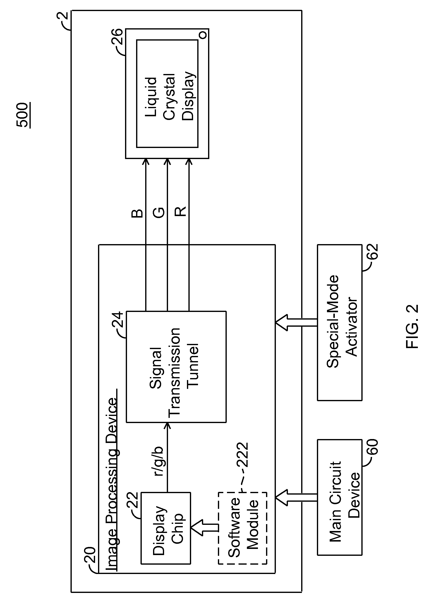
[0019]FIG. 2 is a block diagram of a display system according to the present invention. A computer system 500 disclosed in the present embodiment at least includes a display system 2, a main circuit device 60, and a special-mode activator 62. The display system 2 uses a liquid crystal display system as an example, but does not limit the invention thereby. The display system 2 includes a liquid crystal display 26 and an image processing device 20. The liquid crystal display 26 is to display images. The image processing device 20 outputs a Blue signal B, Green signal G and Red signal R to the liquid crystal display 26 for displaying thereon. The image processing device 20 includes a display chip 22 and a signal transmission tunnel 24. The display chip 22 basically receives an image input (not shown), processes the image input for image displaying, and then outputs to the signal transmission tunnel 24. The display chip 22 is capable of performing Gamma correction; the display chip 22 t...

second embodiment

[0025]FIG. 3 is a block diagram of a display system according to the present invention. A computer system 600 disclosed in the present embodiment at least includes a display system 3, a main circuit device 60, and a special-mode activator 62. The display system 3 uses a liquid crystal display system as an example, but does not limit the invention thereby. The display system 3 includes a liquid crystal display 36 and an image processing device 30. The image processing device 30 outputs a Blue signal B, Green signal G and Red signal R to the liquid crystal display 36 for display corresponding images thereon. The image processing device 30 includes a display chip 32 and a signal transmission tunnel 34. The display chip 32, basically receives an image input (not shown), processes the image input for image displaying, and then outputs red / blue / green output data r / g / b to the signal transmission tunnel 34.

[0026]The main circuit device 60, including essential components (such as a CPU (cent...

third embodiment

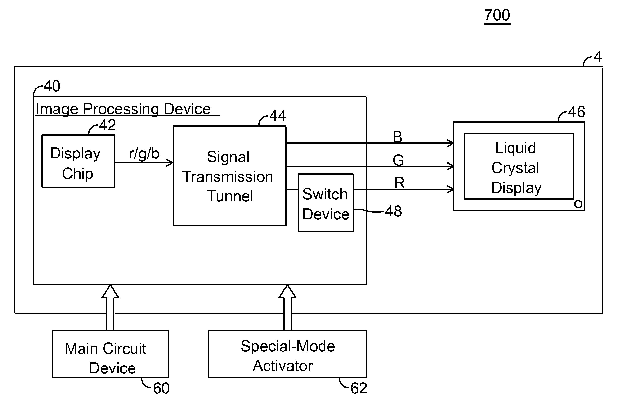
[0029]FIG. 4 is a block diagram of a display system according to the present invention. A computer system 700 disclosed in the present embodiment at least includes a display system 4, a main circuit device 60, and a special-mode activator 62. The display system 4 uses a liquid crystal display system as an example, but does not limit the invention thereby. The display system 4 includes a liquid crystal display 46 and an image processing device 40. The image processing device 40 outputs a Blue signal B, Green signal G and Red signal R to the liquid crystal display 46 for display corresponding images thereon. The image processing device 40 includes display chip 42, a signal transmission tunnel 44, and a switch device 48. The display chip 42, basically receives an image input (not shown), processes the image input for image displaying, and then outputs red / blue / green output data r / g / b to the signal transmission tunnel 44. The switch device 48 is electrically connected between the output...


PUM


Abstract

A display system and driving method thereof are capable of outputting a low luminance of red light, especially through descending a color level of red signals when displayed. The display system includes a display device and an image processing device. The image processing device outputs the red signals to the display device for displaying thereon. The color level of red signals is descended by a display chip or a switch device to allow the display device to display images with low luminance of red light, so that the display device is viewable through a night-vision device.

Description

BACKGROUND OF THE INVENTION[0001]1. Field of the Invention[0002]The present invention relates to a display system and driving method thereof, and more particularly, to a display system and driving method that are capable of descending only the output color level of red signals.[0003]2. Related Art[0004]Generally, a user may view directly by eyes the displayed information on a liquid crystal display. In certain special situations, such as military-use, security-monitoring, hunting, observation of a biological environment at night and etc., the brightness of the liquid crystal display has to be descended to avoid affecting the surroundings. Yet the descended brightness is too low for the user to view the liquid crystal display by eyes directly. Therefore the user has to use a night-vision device to read on the information displayed on the liquid crystal display, such as graphs, characters, images and etc. However, for a common night-vision device with the second or third generation of...

Claims


Application Information

Patent Timeline
Patent Type & Authority Patents(United States)
IPC IPC(8): G09G3/36
CPCG09G5/02G09G3/3611G09G2320/0238G09G2340/14
Inventor SHEN, CHANG-HAN
Owner GETAC TECH CORP
Why Eureka
Try Eureka