
Fishing pole with replaceable illumination element

a technology of illumination element and fishing pole, which is applied in the direction of rods, other angling devices, animal husbandry, etc., can solve the problems of limiting approach, complex approach, and exacerbated moisture problems, and achieves a wider range of operation and long distance.

Active Publication Date: 2012-01-31
COBB KENNY
View PDF87 Cites 32 Cited by
  • Summary
  • Abstract
  • Description
  • Claims
  • Application Information

AI Technical Summary

Benefits of technology

"The fishing pole described in this patent has a hollow handle that can hold a light source. The light source can be a small LED or other light source that fits into the hollow handle. The fishing pole also has a concave reflector at the end of the handle that directs the light towards the end of the pole. A plastic optical fiber runs the length of the pole and is connected to the concave reflector. The plastic optical fiber has a cladding that is scuffed to allow the light to escape and be seen. The fishing pole also has a translucent rod that allows light to pass through and be seen when the pole is moved. The use of plastic optical fiber is preferred over glass because it is more flexible and can withstand cooler temperatures. The technical effect of this invention is to provide a fishing pole with a light source that can be easily inserted and maintained, and that can also rattle and make an auditory signal when the fishing line is tugged."

Problems solved by technology

The former approach is limiting, and the latter approach is complex.
This access can exacerbate issues with moisture, etc.
These glass optical fiber filaments can be quite brittle, which limits their use in applications requiring minimal levels of robustness.
These glass optical fiber filaments are also limited in their ability to acquire and disperse light.
Any or all of the above drawbacks in prior art devices may contribute to the expense of manufacture or repair of an illuminated fishing pole as well as durability issues for such poles.
More brittle glass optical fibers are not suitable for an application allowing rattling of the fiber.

Method used


Image

  • Fishing pole with replaceable illumination element
  • Fishing pole with replaceable illumination element
  • Fishing pole with replaceable illumination element

Examples


Embodiment Construction

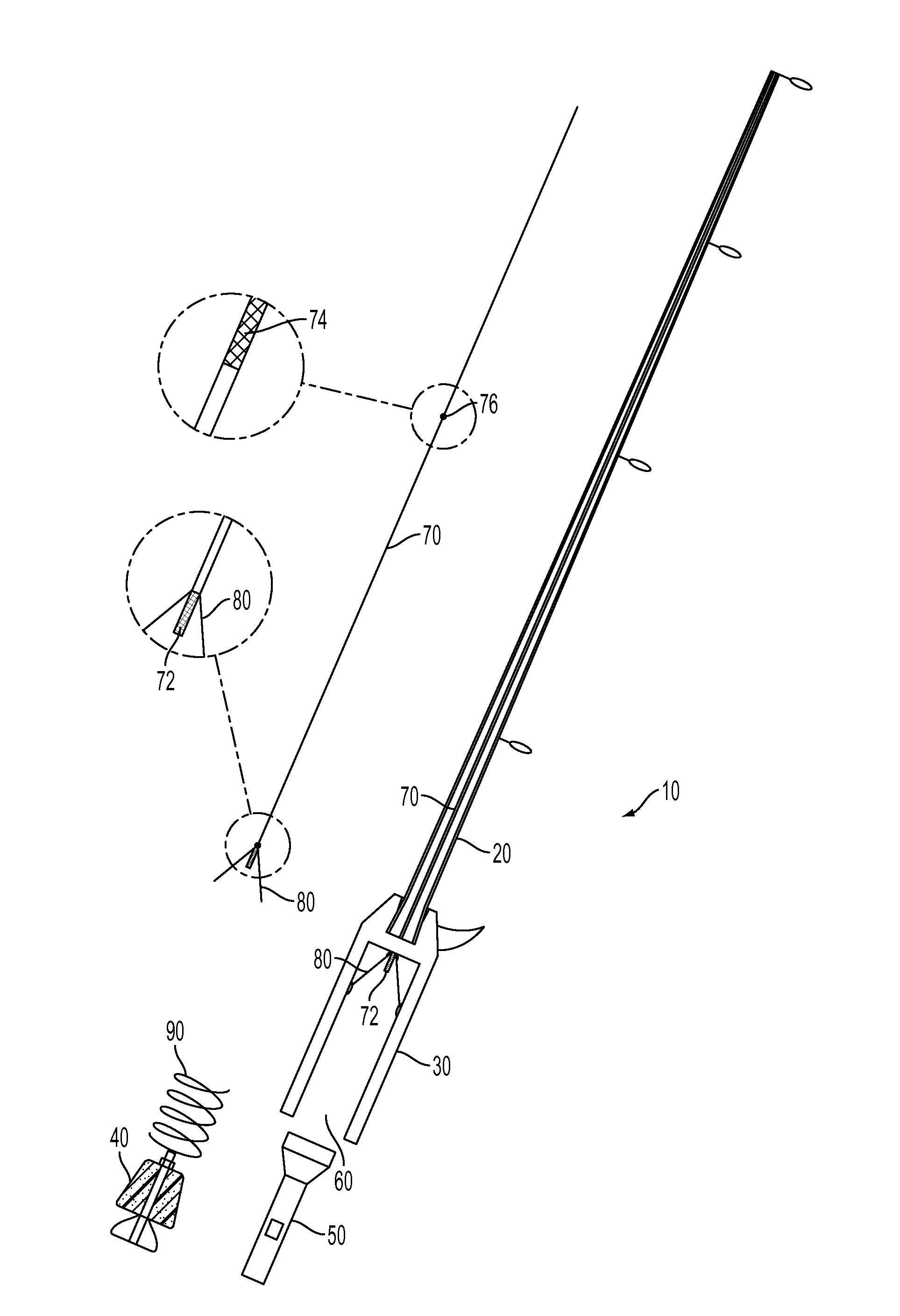
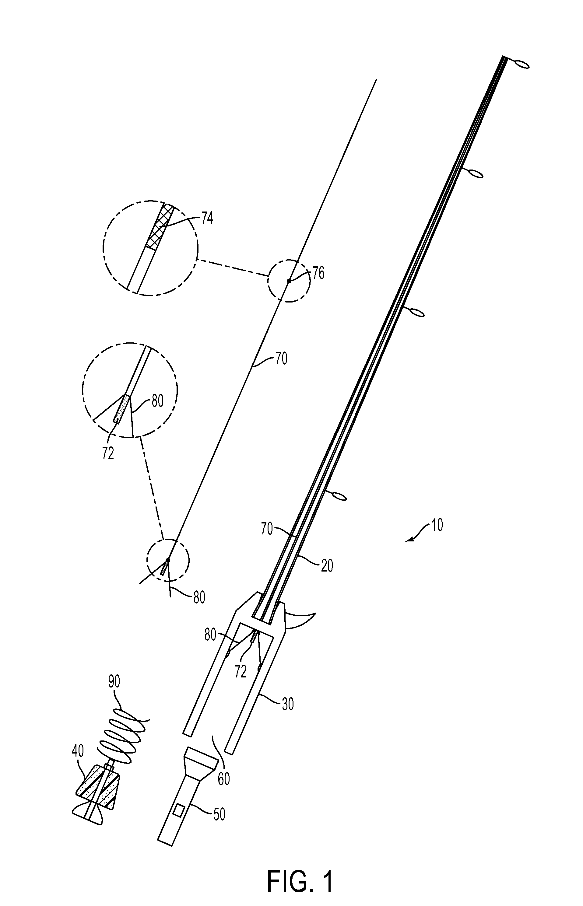
[0017]Referring to FIG. 1, a cross-sectional view of an embodiment of the fishing pole with a replaceable illumination element is shown. The replaceable illumination element is shown both in place within the fishing pole and out along the side of it removed from the fishing pole. The fishing pole has a hollow fishing rod 20 attached to a hollow handle 30. The hollow handle is capable of receiving an independent light source 50 such as a small flashlight. The independent light source 50 may be retained by plug 40, which, in the embodiment of FIG. 1, is a deformable plug which fits into the handle. Spring 90 biases independent light source 50 up into handle 30.

[0018]Within hollow handle 30 is located concave reflector 80. Plastic optical fiber 70 protrudes through concave reflector 80 and also runs the length of hollow fishing rod 20. As may be seen in the enlarged view, the end 72 of plastic optical fiber 70 that protrudes through concave reflector 80 is scuffed on its surface. This ...


PUM


Abstract

A fishing pole has a hollow handle and a hollow rod with their interior chambers in communication with each other. The hollow handle can receive an independent light source and also houses a concave reflector. The hollow rod contains a plastic optical fiber which extends along the length of the hollow rod and extends into the hollow handle through the concave reflector. The hollow rod has at least some portions that are translucent. The plastic optical fiber is scuffed on its end where it protrudes through the concave reflector and also in sections within the hollow rod. An independent light source inserted into the hollow handle is directed toward the concave reflector and light is directed into the plastic optical fiber, transmitted to the hollow rod, and diffused out into the hollow rod and then outside. The plastic optical fiber also rattles when the rod is moved.

Description

BACKGROUND[0001]Fishing is a common and popular pastime and profession. A large number of people participate in the activity of fishing using a fishing pole, fishing line, and hook. Frequently, a fishing line is cast out into the water, and the fishing pole set to be left by itself while being visually monitored. In this way, several fishing poles may be used at the same time. Fishing at night, however, introduces difficulties with visibility. When fishing at night, it is difficult to adequately monitor the fishing pole. Also, even when a fisherman becomes aware that there is a fish on the line, quick action requires visibility of the handle of the fishing pole. Various arrangements and developments have been made to enable fishing poles to be monitored, either by visual cues or by audible cues. However, many of these arrangements are overly complex, difficult to repair, or limited to specific light sources. Embodiments of the present invention provide a means for monitoring the fis...

Claims


Application Information

Patent Timeline
Patent Type & Authority Patents(United States)
IPC IPC(8): A01K97/12A01K87/00
CPCA01K87/007
Inventor COBB, KENNY
Owner COBB KENNY
Learn More