Method of manufacturing a graded-index plastics optical fiber

a technology of plastics and optical fibers, applied in the field of manufacturing a can solve the problems of difficult manufacturing of such plastics optical fibers, slow and not very reproducible methods, and the inability to manufacture graded index plastics optical fibers

Inactive Publication Date: 2003-06-10
NEXANS
View PDF3 Cites 37 Cited by
  • Summary
  • Abstract
  • Description
  • Claims
  • Application Information

AI Technical Summary

Benefits of technology

The method of manufacture of the invention seeks to manufacture graded-index plastics optical fi

Problems solved by technology

Manufacturing such plastics optical fibers is difficult in that it is necessary to obtain a distribution of said compound that varies from the core to the periphery of a plastics optical fiber.
All of the above manufacturing method

Method used


Image

  • Method of manufacturing a graded-index plastics optical fiber
  • Method of manufacturing a graded-index plastics optical fiber
  • Method of manufacturing a graded-index plastics optical fiber

Examples


second embodiment

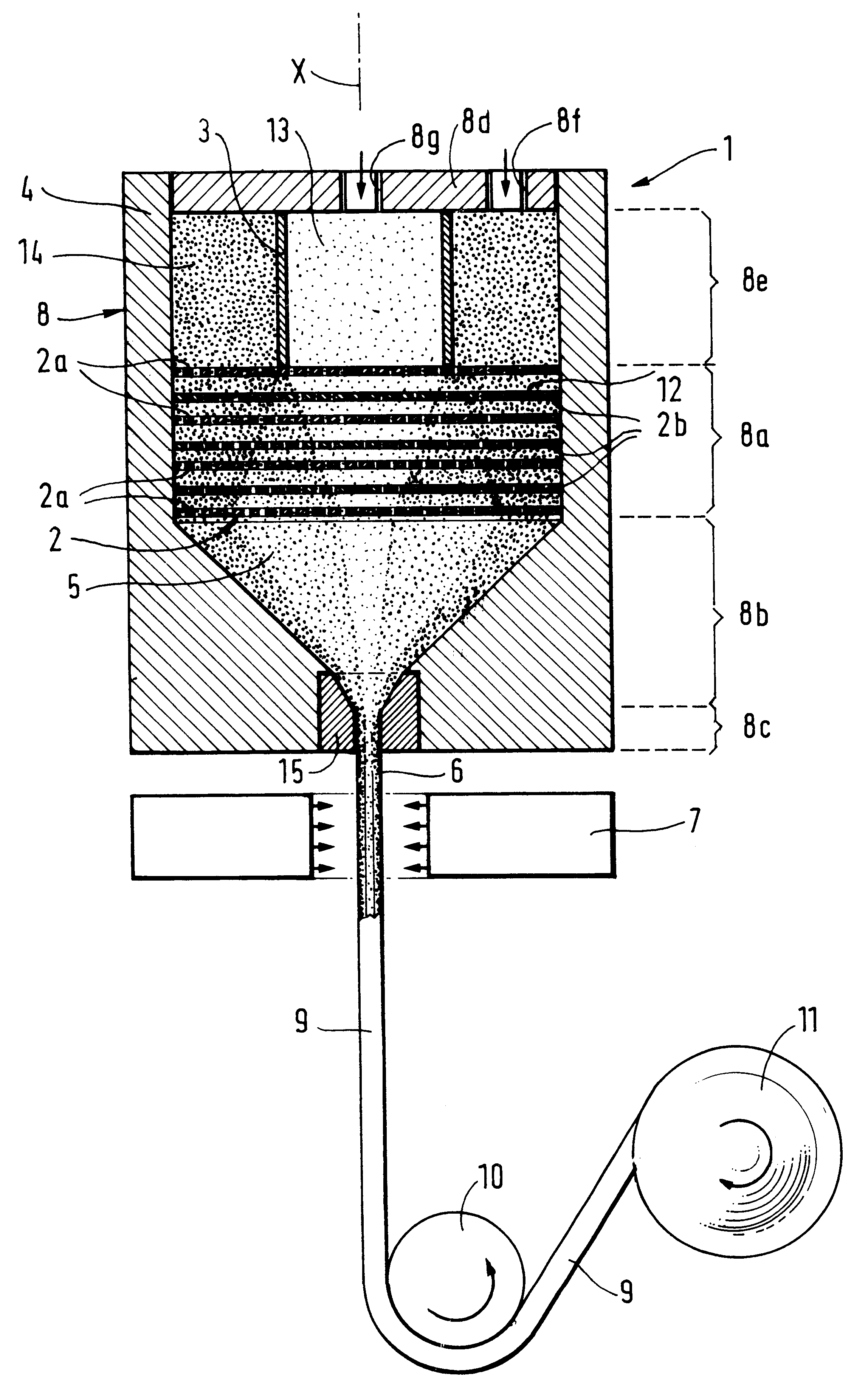
In a second embodiment, the static mixer 1' does not comprise a set 2 of plates (2a, 2b) like the mixer 1 of FIG. 1, but instead comprises a set 16 of fixed baffles represented by symbolic cross-shapes in FIG. 4. These baffles are zigzag passages which the compositions 13 and 14 are constrained to follow, thereby achieving progressive mixing 5'. The shape and size of the set 16 of baffles leads directly to the index profile of a graded-index plastics optical fiber 6' as obtained in this way. The profile is of the same type as that shown in FIG. 3.

third embodiment

In a third embodiment, the static mixer 1" does not have a set 2 of plates (2a, 2b) of the mixer 1 of FIG. 1, but instead has a cartridge 17 of beads 18, as shown in FIG. 5. The resulting mixture is referenced 5". The beads 18 can all be identical in diameter, as shown in FIG. 5, or they can be of different diameters either individually or in groups as compared with adjacent individual beads or groups of beads. Under such circumstances, the gradient of the mixture 5" obtained in this way depends on the diameter and the disposition of the beads 18 within the cartridge 17. A graded-index plastics optical fiber 6" is thus obtained which is photo-cured by the source 7 so as to become a polymerized optical fiber 9". The profiles of the plastics optical fibers 6" and 9" are of the same type as that shown in FIG. 3.

FIG. 6 is a highly diagrammatic section view on a plane containing a central axis X of a dynamic mixer 24. Mixing 5" is provided by mixing means 26 comprising a solid shaft 19 o...

example 1

Manufacturing a Reactive Polymer of the Poly (.alpha. fluoro) (meth)acrylate type.

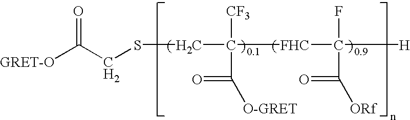
A photoreactive polymer (P1) is made having the following formula: ##STR1##

where GRET represents the photo-curable group:

--CH.sub.2 --CH(OH)--CH.sub.2 --O--CO--C(CH.sub.3).dbd.CH.sub.2

and where Rf represents the CH(CF.sub.3).sub.2 group which serves to adjust refractive index.

This is done initially by synthesizing a precursor polymer, and then by introducing the photoreactive groups on the precursor polymer.

To synthesize the precursor polymer, the following raw materials were used: two monomers, hexafluoroisopropyl .alpha.,.beta.-difluoroacrylate and acrylic .alpha.-trifluoromethyl acid, the transfer agent being thioglycolic acid and the initiator being 4,4'-azobis (4-cyano) pentanoic acid (ACPA) with quantities of 1 mole of transfer agent per 20 moles of monomer and 0.2 moles of initiator per 20 moles of monomer. Copolymerization was triggered thermally at a temperature of about 60.degree. C. In a var...


PUM

PropertyMeasurementUnit
Timeaaaaaaaaaa
Timeaaaaaaaaaa
Viscosityaaaaaaaaaa

Abstract

A method and apparatus for manufacturing a graded-index plastics optical fiber of continuously varying index profile, starting from a particular polymer P and a particular compound M1, the method including the steps of: preparing two compositions of different refractive index, allowing the compositions to diffuse one into the other, and spinning the compositions so as to obtain the fiber, wherein, prior to extrusion, the two compositions are subjected to active mixing, and extrusion of the fiber is followed by curing.

Description

The present invention relates to a method of manufacturing a graded-index plastics optical fiber.Graded-index plastics optical fibers, suitable for use in a spectrum range covering the visible and the near infrared, are advantageous in that they can be applied to broadband access networks. A graded-index plastics optical fiber can comprise at least one polymer and at least one other compound, with the polymer content being substantially the same throughout the fiber, while the concentration of the other compound varies from the core to the periphery of the fiber in such a manner as to form the desired index gradient. Said compound, which can be referred to as a "dopant" or as a "diluant", comprises at least one substance. Manufacturing such plastics optical fibers is difficult in that it is necessary to obtain a distribution of said compound that varies from the core to the periphery of a plastics optical fiber. The fiber needs to have a refractive index profile of the graded-index ...

Claims


Application Information

Patent Timeline
IPC IPC(8): D01F8/04D01F8/10D01D5/34G02B6/028G02B6/02B29C47/00B01F5/06B01F7/00G02B6/00B01F7/18B01F15/06B29B7/32B29B7/44B29C47/88B29C48/30C08F290/12
CPCB01F5/0683B29C47/0898B01F5/0695B01F5/0696B01F7/007B01F7/18B01F15/065B29B7/325B29B7/44B29C47/0014B29C47/0026D01D5/34D01F8/10G02B6/02038B29C47/362B29C47/363B01F5/0688B29C47/00B29C48/05B29C48/00B29C48/10B29C48/154B29C48/28B29C48/34B29C48/362B29C48/363B01F25/451B01F25/45241B01F25/4524B01F25/4521B01F27/2122B01F27/90B01F35/92G02B6/00
Inventor PERRIN, BERNARDPASTOURET, ALAINMORICHERE, DOMINIQUEANDRIEU, XAVIER
Owner NEXANS
Why Eureka
Try Eureka