Resin cage for ball bearing

a technology of ball bearings and cages, which is applied in the direction of shafts and bearings, rotary bearings, rolling contact bearings, etc., can solve the problems of safety and appearance, variation in resin cooling time, and deterioration of resin flowability at injection molding, so as to improve the moldability of cages, uniform thickness of cages, and suppress internal stress.

Active Publication Date: 2012-01-31
JTEKT CORP
View PDF21 Cites 1 Cited by
  • Summary
  • Abstract
  • Description
  • Claims
  • Application Information

AI Technical Summary

Benefits of technology

[0005]The invention is accomplished in view of such circumstances. An object of the invention is to provide a resin cage for a ball bearing, which can properly suppress the deterioration of the flowability of resin at the molding thereof and the generation of internal stress due to the presence of a thickness difference among parts of the cage to thereby enhance the moldability of a cage that is a resin molded-article.
[0006]Also, another object of the invention is to provide a resin cage for a ball bearing, which can increase the substantial volume of the internal space of the ball bearing, as compared with the conventional resin cages, in the case of mounting the resin cage therein by reducing the volume of the resin cage and which can increase an amount of grease which can be enclosed into the internal space while suppressing the leakage of the grease to be enclosed thereinto.

Problems solved by technology

Such a sharp change in the thickness may deteriorate the flowability of resin at injection molding with the result of causing injection-molding defects, such as sink marks and air bubbles.
In addition, the presence of a thickness difference may cause variation in cooling-down time of resin at injection molding with the result of generation of internal stress and occurrence of shape distortion.
However, in a case where grease leaks out of the internal space, problems of safety and appearance occur.
However, it becomes problematic that the substantial volume of the internal space is reduced by inserting the resin cage into the ball bearing.

Method used


Image

  • Resin cage for ball bearing
  • Resin cage for ball bearing
  • Resin cage for ball bearing

Examples


Embodiment Construction

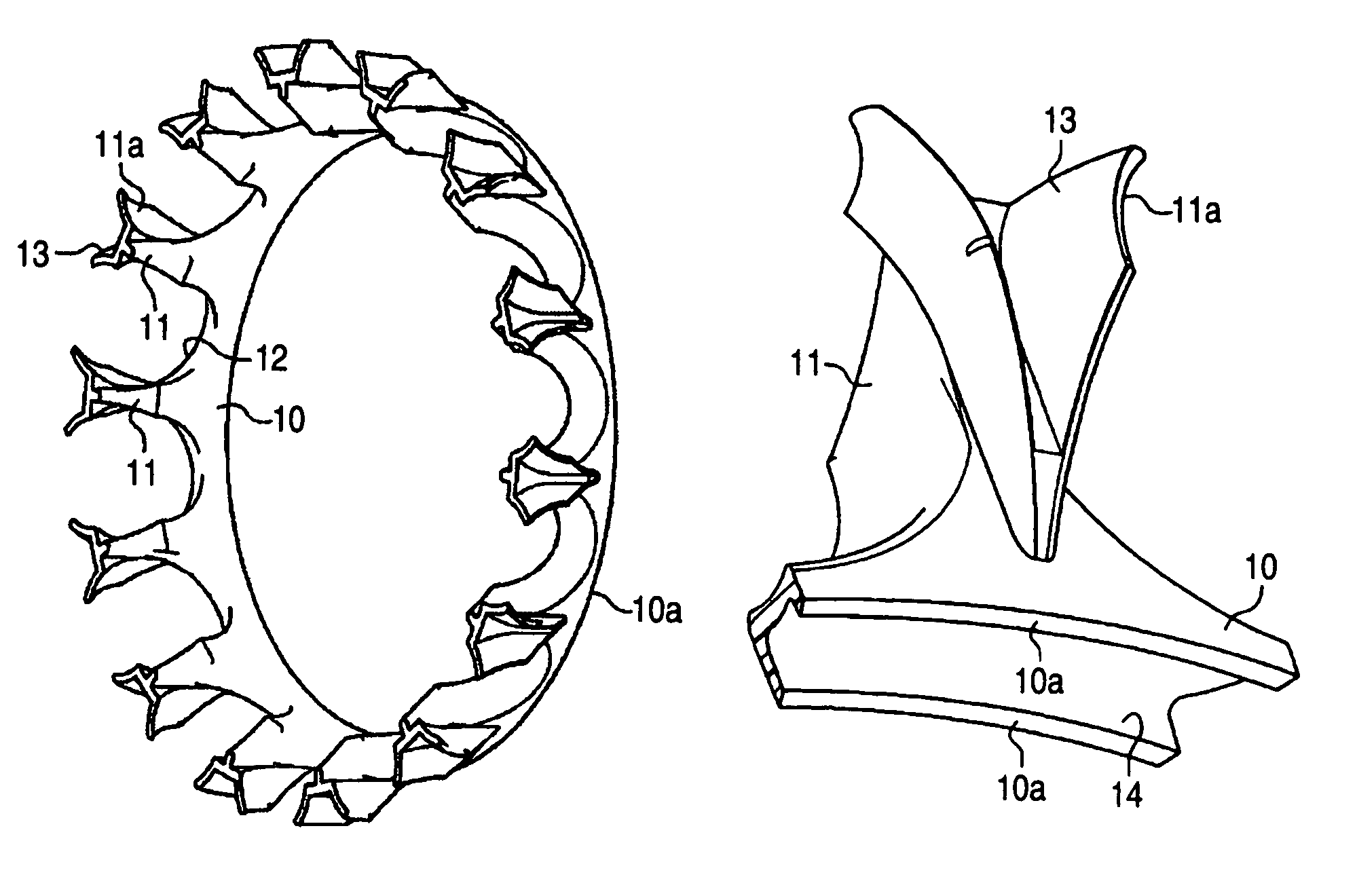
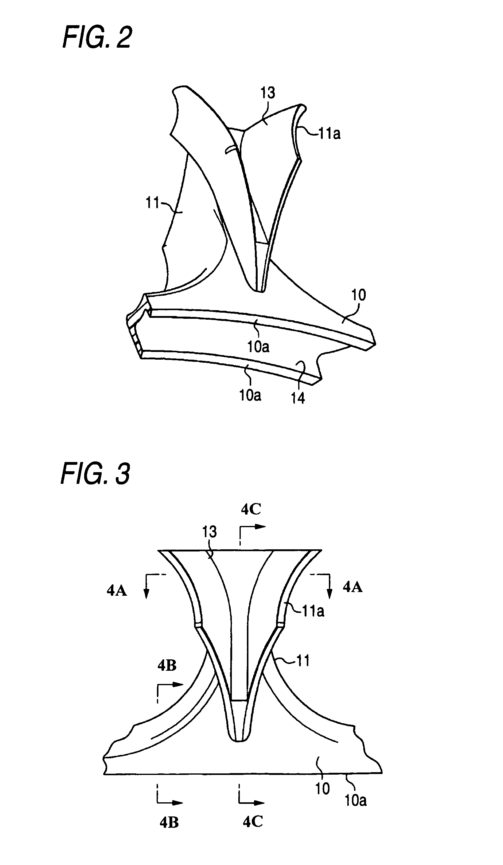
[0028]Hereinafter, a resin cage for a ball bearing according to an embodiment of the invention will be-described in detail with reference to FIGS. 1A to 4C. The cage according to the present embodiment is formed by resin injection molding, and is employed in an angular contact ball bearing.

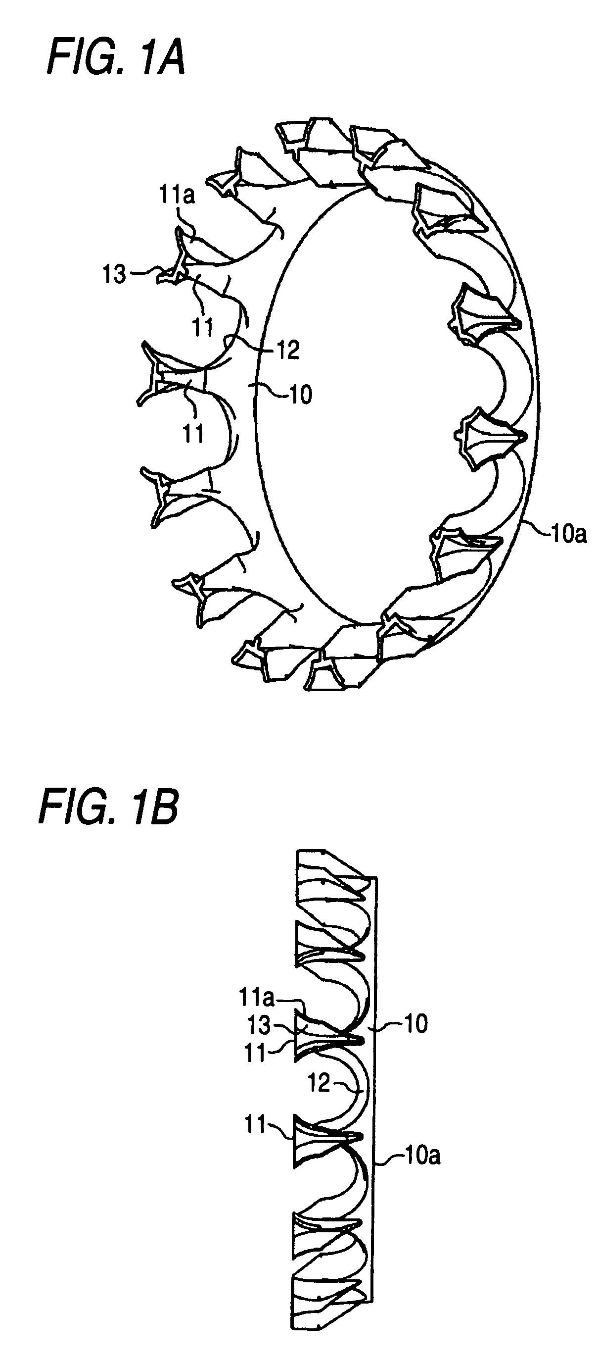
[0029]FIG. 1A is a perspective view illustrating the perspective structure of such a resin cage for the ball bearing according to an embodiment of the invention. FIG. 1B is a side view illustrating the side structure of the resin cage for the ball bearing according to the embodiment of the invention. As illustrated in FIGS. 1A and 1B, the resin cage is formed into a substantially crown-like shape, and includes an annular base portion 10, and a plurality of claw portions 11 (the number of the claw portions 11 is, e.g., 14 in an example illustrated in FIGS. 1A and 1B) which are formed to be arranged at constant intervals on the circumference of the base portion 10 and to protrude therefrom. A concav...


PUM


Abstract

It is a cage that is formed of a resin and that holds balls serving as rolling elements. The cage includes an annular base portion, and a plurality of claw portions that are formed to be arranged at constant intervals on the circumference of the base portion and to protrude therefrom. A pocket for accommodating the ball is formed between each pair of adjacent ones of the claw portions. In the resin cage for a ball bearing, thinning recesses are formed in end parts 11a of the claw portions and a rear surface of the base portion, respectively.

Description

BACKGROUND OF THE INVENTION[0001]The present invention relates to a resin cage to be employed in a ball bearing.[0002]A ball bearing includes an inner ring, an outer ring, a plurality of balls interposed therebetween, and a cage which holds each of the adjacent balls to be separated from each other In recent years, a resin cage formed by injection molding has been widely used as a cage for such a ball bearing. For example, JP-A-7-190069 describes an example of a resin cage for an angular contact ball bearing. As illustrated in FIG. 6, such a resin cage is formed substantially like a crown, and includes an annular base portion 20, and a plurality of claw portions 21 that are formed to be arranged on the circumference of the base portion 20 at constant intervals and to protrude therefrom. A concave-sphere-like pocket 22 for accommodating a ball is formed between each pair of the adjacent claw portions 21.[0003]Meanwhile, for the convenience of accommodating a spherical object in each ...

Claims


Application Information

Patent Timeline
Patent Type & Authority Patents(United States)
IPC IPC(8): F16C33/38F16C33/56F16C33/41
CPCF16C33/416F16C33/6614F16C19/185F16C33/418
Inventor TAKADA, YOSHITOHARADA, KATSUYUKITSUZAKI, YOUICHIHAKATA, TOSHIHIRODEGUCHI, MASARU
Owner JTEKT CORP
Why Eureka
Try Eureka