Mating of optical fibers having angled end faces

a technology of mating fibers and end faces, which is applied in the field of mating fibers prepared to have angled end faces, can solve the problems of reducing the service life of the connection, increasing the reflectance at the splice, and deteriorating the optical signal, and achieves the effect of satisfying the optical connection

Active Publication Date: 2012-01-31
COMMSCOPE TECH LLC
View PDF7 Cites 37 Cited by
  • Summary
  • Abstract
  • Description
  • Claims
  • Application Information

AI Technical Summary

Benefits of technology

[0011]Generally, the present invention provides for a method for mating optical fibers, a fiber optic connector, and a fiber optic subassembly in which mating fibers have angled end faces joined by index matching fluid, but in which the angle end faces of the fibers are positioned relative to one another in rotationally misaligned relationship. In other words, the fibers are mated in positions other than in the precise rotationally aligned position (180 degrees out of phase in rotation about a common optical axis, + / −15 degrees). Accordingly, the need to precisely align mating fibers, as widely recognized in the prior art, is avoided, and yet a satisfactory optical connection may be obtained. Further, the present invention permits random relative rotational orientation of mating fibers, thus eliminating the need to precisely align fibers for mating purposes.

Problems solved by technology

Frequently, however, connectors must be terminated in the field where such facilities and personnel are not available.
However, as the connector temperature departs from the ambient, the refractive index of the gel changes, which increases the reflectance at the splice.
This increase can cause degradation of the optical signal, particularly when coherent light sources are used for signal propagation.
Providing an angled end face tends to cause light reflected at the fiber interface to be reflected at an angle into the cladding of the fiber, rather than back down the fiber core where it can interfere and diminish forward-propagating optical signals.
Keeping the fibers / ferrules properly oriented rotationally is complicated by the fact that the angle of the cleave cannot be perceived by the naked eye.
Accordingly, to avoid rotational misalignment, complex and relatively expensive tools and techniques were developed.

Method used


Image

  • Mating of optical fibers having angled end faces
  • Mating of optical fibers having angled end faces
  • Mating of optical fibers having angled end faces

Examples


Embodiment Construction

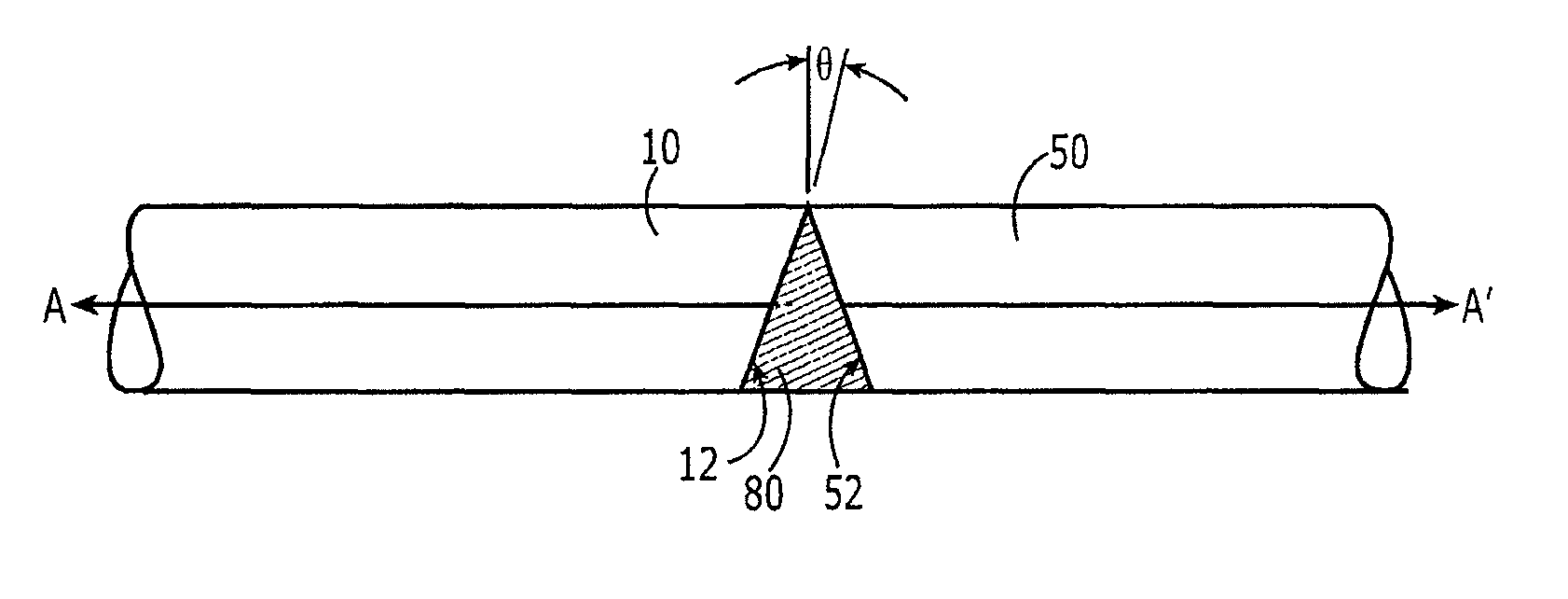
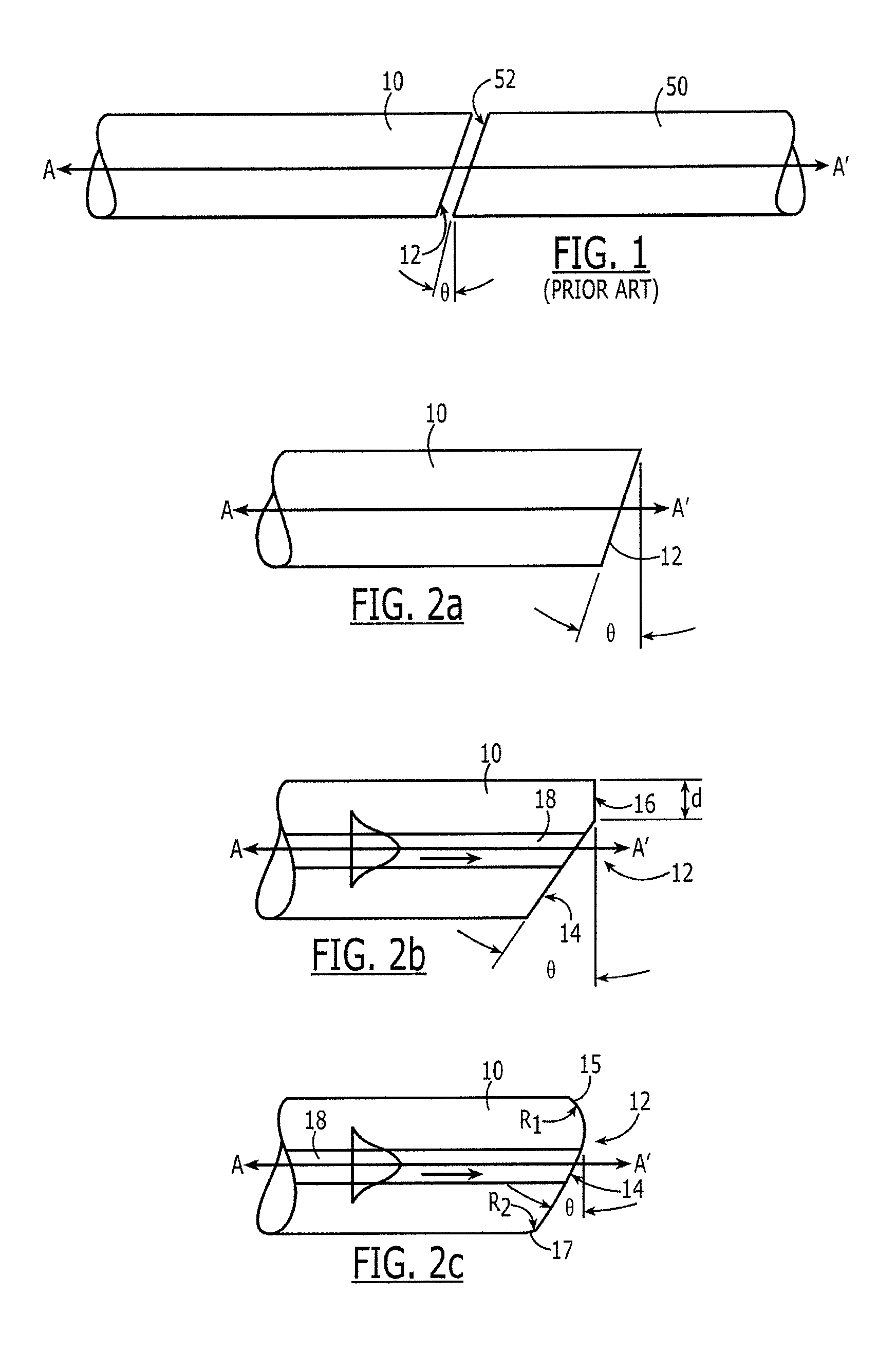
[0026]Referring again to FIG. 1, exemplary optical fibers are shown in diagrammatic side view. This arrangement is typical of the prior art in that both the launch and receive fibers 10, 50, have similarly-formed, referred to herein as “matched” or “matching,” angle-cleaved end faces 12, 52. In the example shown, these end faces 12, 52 are substantially flat, as is typical, for example, of a mechanically cleaved fiber, as well known in the art. Further, these end faces are “angle-cleaved,” or “angled.” As used herein, the terms “angle-cleaved” and “angled” refer to an end face that has a substantially-planar portion that is formed at an acute angle θ relative to a plane normal to the optical axis of the fiber, as shown in FIG. 1.

[0027]Further, the exemplary fibers 10, 50 of FIG. 1 are shown arranged in a typical prior art arrangement for satisfactory optical coupling in that they are positioned in conventional rotational alignment. As user herein “rotational alignment” and “rotation...


PUM

PropertyMeasurementUnit
angular rotationaaaaaaaaaa
of rotationaaaaaaaaaa

Abstract

A method for mating optical fibers, a fiber optic connector, and a fiber optic subassembly are provided in which mating fibers have angled end faces joined by index matching fluid, but in which the angled end faces of the fibers are positioned relative to one another in rotationally misaligned relationship. Applicants discovered unexpectedly that optical fibers can be spliced, to provide satisfactory optical connections, without the need for matched cleaves, and without the need for precise rotational alignment of the cleaves, provided that angled end faces are provided on both the launch and receive fibers and that index matching gel is provided between the angled end faces. Thus, the fibers are mated in positions other than in the precise rotationally aligned position previously believed essential to adequate optical performance. Angled end faces may be positioned less than 165 degrees out of phase.

Description

FIELD OF INVENTION[0001]The present invention relates generally to mating of optical fibers, and more particularly, to mating fibers prepared to have angled end faces.BACKGROUND[0002]Fiber optic communication systems include optical connectors that mate segments of optical fibers. The principal function of an optical fiber connector is to hold a fiber end such that the core of the fiber is axially aligned with the optical path of the fiber component, etc. to which the connector is mated, e.g., so that light from the one fiber is optically coupled to another. This is achieved by holding the end of the fiber such that the core of the fiber is axially aligned with the optical pathway of the mating fiber. By way of example, optical fibers may be mated at a splice, e.g., within a single connector, or may be mated between one or more connectors or optoelectronic devices.[0003]To facilitate an effective optical coupling between a connector and another connector or other device, the end fac...

Claims


Application Information

Patent Timeline
Patent Type & Authority Patents(United States)
IPC IPC(8): G02B6/32
CPCG02B6/382G02B6/3822Y10T29/49195
Inventor GURRERI, MICHAEL L.
Owner COMMSCOPE TECH LLC
Why Eureka
Try Eureka