Broom assembly

a technology of brooms and assembly rods, which is applied in the direction of screw threaded joints, couplings, and rod connections, can solve the problems of long assembly time, complicated detachment of the head structure from the rod structure, and inconvenience in cleaning cloth removal from the circular disc, so as to save manufacturing costs, prevent untimely disengaging, and simple structure

Inactive Publication Date: 2012-02-07
DIKAI INT ENTERPRISE
View PDF5 Cites 16 Cited by
  • Summary
  • Abstract
  • Description
  • Claims
  • Application Information

AI Technical Summary

Benefits of technology

[0008]Therefore, the object of the present invention is to provide a broom assembly which includes lesser components and simpler structure so as to overcome the long assembly time and high manufacturing expense during the mass production of the prior art broom assembly.
[0011]As explained above, the broom assembly of the present invention does not include the circular disc of the prior art, thereby economizing the manufacturing expense when compared to the prior art technology. In addition, the rod structure includes an elongated handgrip rod and when it is desired to remove the handgrip rod from the head structure, the sweeper's leg only needs to step on the head structure while the hand grips on the top end of the handgrip rod. Afterward, the handgrip rod is swung to one lateral side of the head structure without removing the leg from the head structure so as to permit detachment of the handgrip rod from the head structure. It requires a smaller storage space for storing the broom assembly of the present invention since the handgrip rod is easily detached from the head structure.
[0012]Moreover, the engagement of the coupling member relative to the resilient ribs within the reception chamber is simple in structure, thereby economizing a relatively large amount of components and consequently lowers the assembly time and the manufacturing expense.

Problems solved by technology

It is very inconvenient to remove the cleaning cloth from the circular disc, because the retention ring must be removed first from the circular disc by using two hands.
Thus, the detachment of the head structure from the rod structure is complicated.
In FIG. 2 of the aforesaid utility patent, it can be observed that there are a lot of components between the connecting head I and the circular disc and the assembly thereof is complicated, thereby resulting in long assembly time and high manufacturing expense.

Method used


Image

  • Broom assembly
  • Broom assembly
  • Broom assembly

Examples


Embodiment Construction

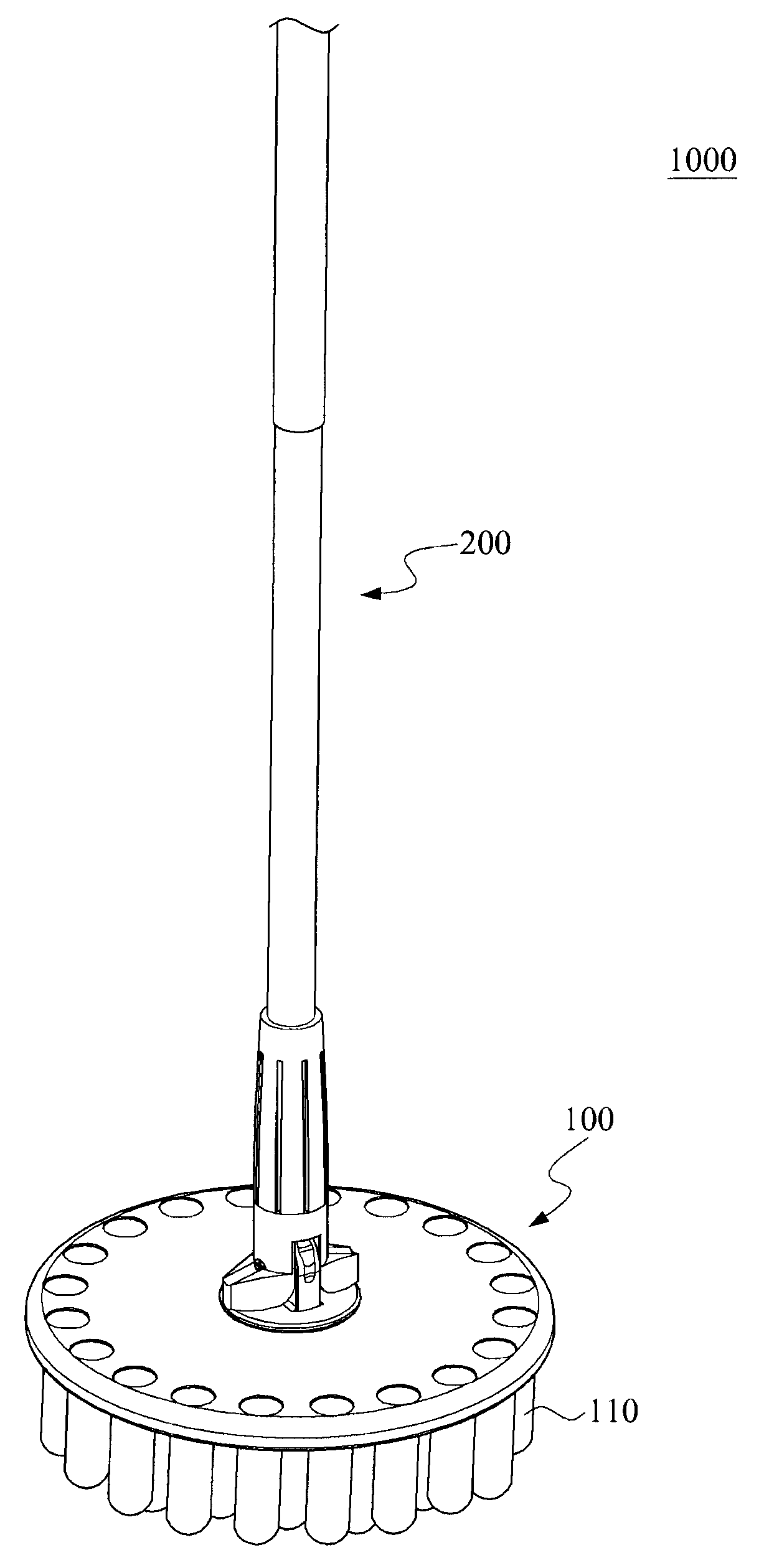
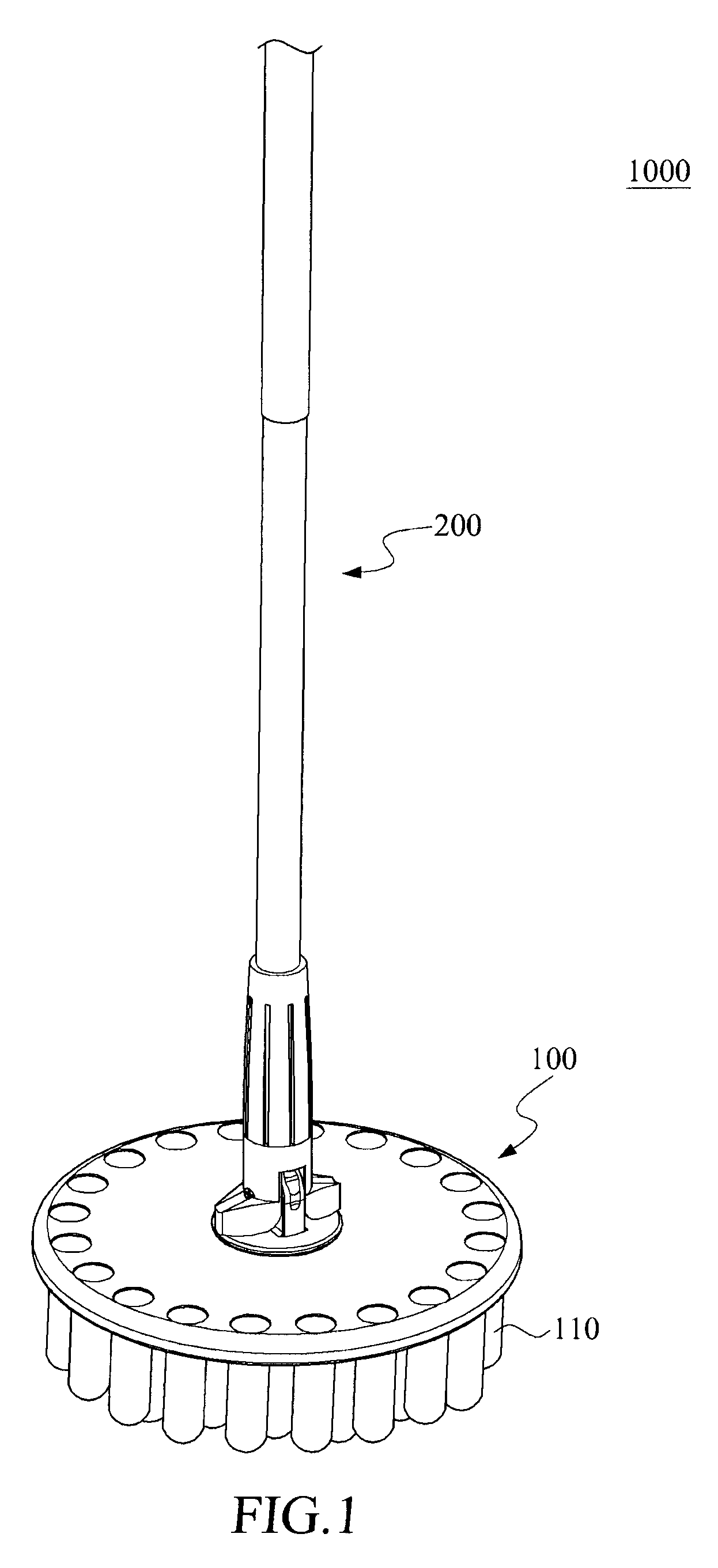
[0018]FIG. 1 shows a perspective view of a broom assembly 1000 of the present invention to include a head structure 100 and a rod structure 200. The head structure 100 is circular in shape and includes a cleaning member 110 for sweeping the floor. The rod structure 200 is elongated and is connected to the head structure 100 such that the head structure 100 is rotatable relative to the rod structure 200 and that the rod structure 200 can be swung to one lateral side so as to be inclined relative to the head structure 100.

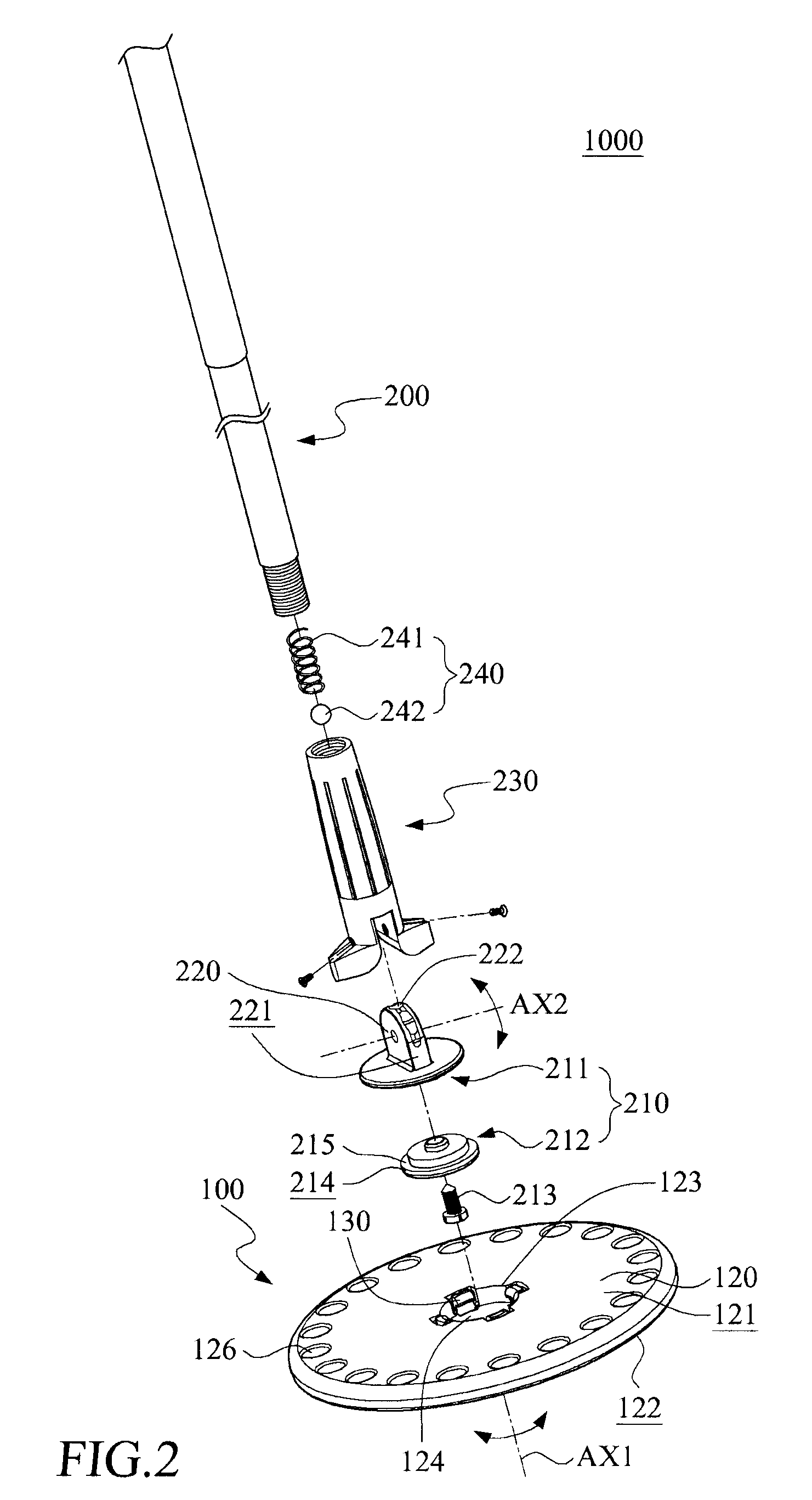
[0019]FIG. 2 is an exploded view of the broom assembly 1000 of the present invention, wherein the cleaning member 110 is removed therefrom. FIG. 3 shows is a fragmentary sectional view of the broom assembly 1000 of the present invention. As illustrated, the head structure 100 includes a base 120, a plurality of resilient ribs 130 and a cleaning member 110 (see FIG. 1). The base 120 is a circular disc having a coupling face 121 formed with a reception chamber 124 and ...


PUM


Abstract

A broom assembly includes a head structure and a rod structure. The head structure includes a base having a coupling face formed with a reception chamber and an opening for access into the reception chamber, and a plurality of resilient ribs provided at the periphery confining the opening and extending inwardly and radially toward a center axis of the opening. The rod structure includes a coupling member provided partially, rotatably and detachably within the reception chamber in the coupling face of the base. When the coupling member is detachably received within the reception chamber, the coupling member biases against and engages the resilient ribs so as to be prevented untimely disengaging from the base.

Description

[0001]This application claims the benefits of the Taiwan Patent Application Serial NO. 098201053 filed on Jan. 20, 2009, the subject matter of which is incorporated herein by reference.BACKGROUND OF THE INVENTION[0002]1. Field of the Invention[0003]The present invention relates to a broom assembly, more particularly to a broom assembly including a head structure and a rod structure that is rotatable relative to and is adapted to be detached from the head structure with ease.[0004]2. Description of the Prior Art[0005]According to ROC (Republic of China) utility patent number M290028, a broom assembly is disclosed to include a head structure of a circular shape and a handgrip rod (consisting of an elongated rod and a handle) that is rotatable relative to the head structure. When the sweeper grips the handgrip rod and sweeps the floor, the head structure rotates relative to the handgrip rod and simultaneously cleans the floor.[0006]In addition, the head structure includes a circular di...

Claims


Application Information

Patent Timeline
Patent Type & Authority Patents(United States)
IPC IPC(8): A46B5/00
CPCA46B5/0058A46B5/0075A46B7/04F16C11/06A46B2200/302Y10T403/32024Y10T403/68
Inventor LIN, CHANG-ITING, MING-CHEPENG, HUNG-CHUN
Owner DIKAI INT ENTERPRISE
Why Eureka
Try Eureka