Checker-equipped door hinge device for vehicle

a technology for door hinges and vehicles, which is applied in the direction of door/window fittings, multi-purpose tools, construction, etc., can solve the problems of difficult arrangement of door hinge devices in a narrow and small space between the body and the door of an automobil

Inactive Publication Date: 2012-02-07
RIKEN KAKI KOGYO CO LTD
View PDF9 Cites 21 Cited by
  • Summary
  • Abstract
  • Description
  • Claims
  • Application Information

AI Technical Summary

Benefits of technology

[0009]With the first feature of the present invention, the inner peripheral surface and the outer peripheral surface of the outer cylinder are eccentric to each other, and the checking-force generating mechanism is provided in the thick wall portion, having the large distance between the inner peripheral surface and the outer peripheral surface of the outer cylinder, of the outer cylinder. This configuration makes it possible to efficiently arrange the checking-force generating mechanism with a large volume in the outer cylinder without the diameter of the outer cylinder being particularly increased, and thus achieve a compact checker-equipped door hinge device. Accordingly, the checker-equipped door hinge device can be easily arranged even in a narrow and small space between the body and the door.
[0011]With the second feature of the present invention, the checking-force generating mechanism can be easily provided in the thick wall portion of the outer cylinder.
[0013]With the third feature of the present invention, the outer cylinder brings the inner peripheral surface of the thin wall portion into pressure contact with the slider by receiving the compression repulsive force of an elastic member. When the inner cylinder and the outer cylinder relatively rotate, the slider slides with respect to the inner peripheral surface of the thin wall portion side. This configuration makes it possible to desirably adjust the opening and closing feeling of the door by changing the material properties, the surface roughness, the sliding area, and the like, of the slider.

Problems solved by technology

As a result, a problem may possibly occur that such door hinge device is difficult to arrange in a narrow and small space between the body and the door of an automobile.

Method used


Image

  • Checker-equipped door hinge device for vehicle
  • Checker-equipped door hinge device for vehicle
  • Checker-equipped door hinge device for vehicle

Examples


first embodiment

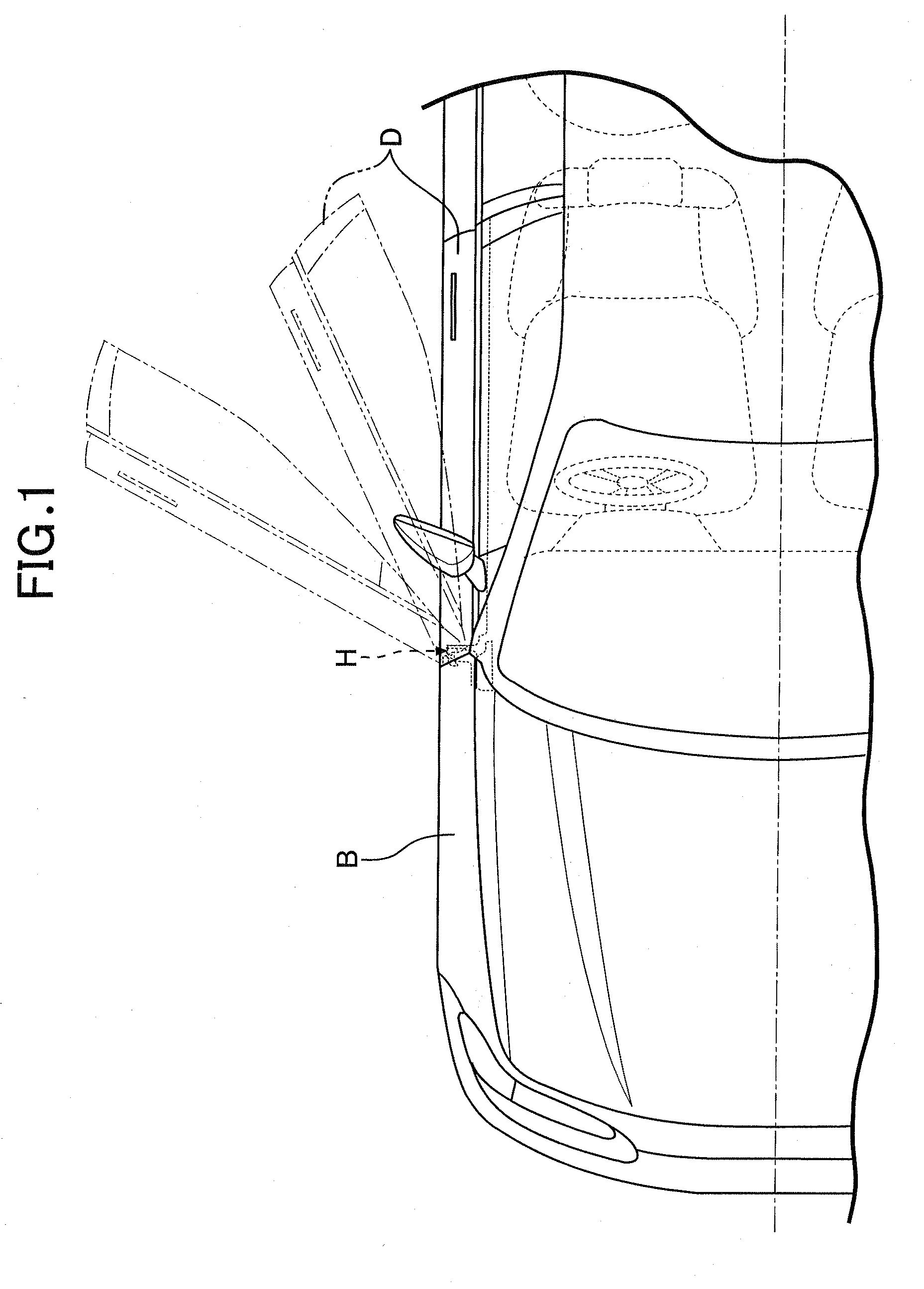
[0026]Firstly, the present invention will be described. In FIG. 1, a door D is rotatably attached to a body B of an automobile with a door hinge device H interposed therebetween so that the door D can open and close the door opening of the automobile.

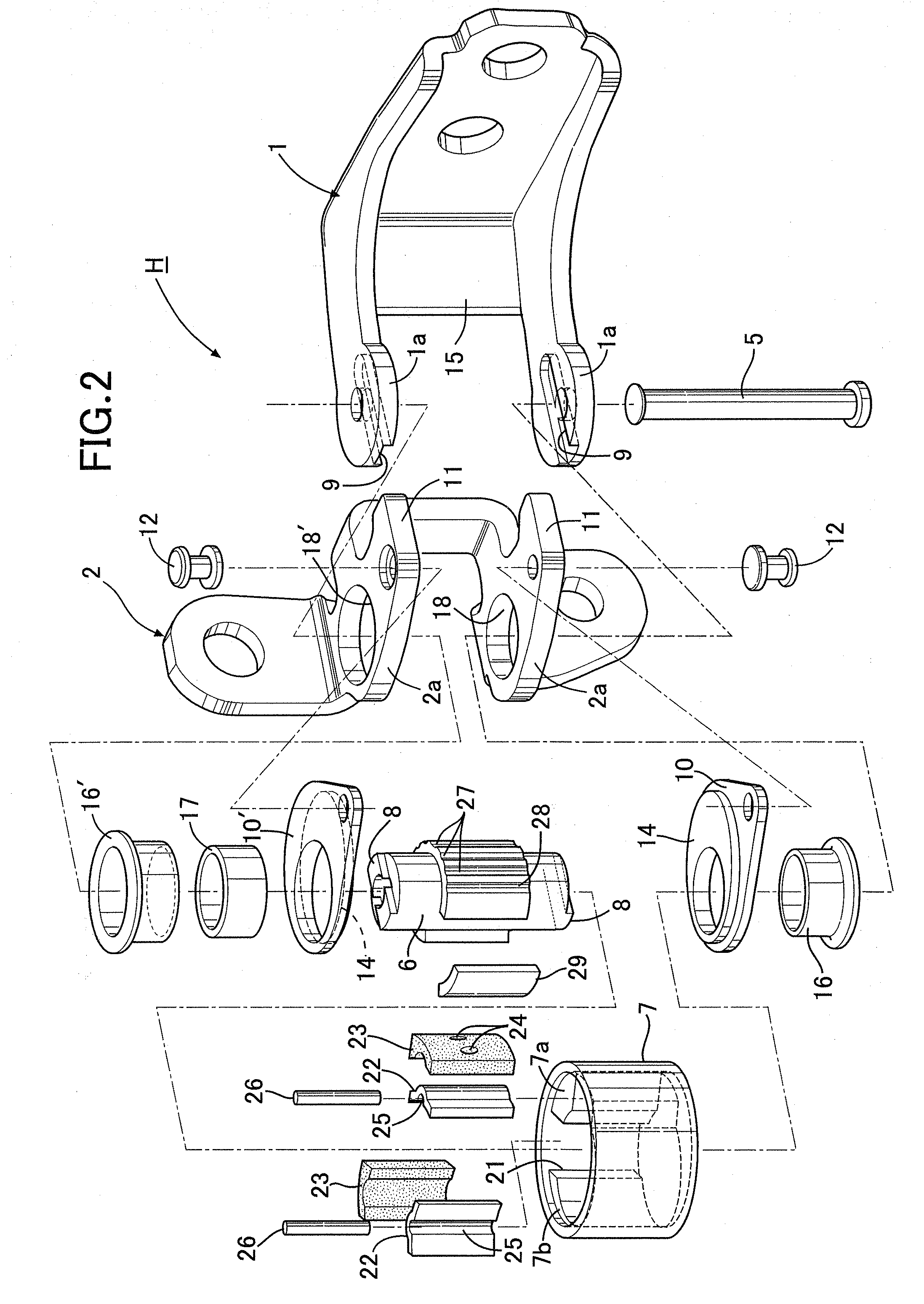
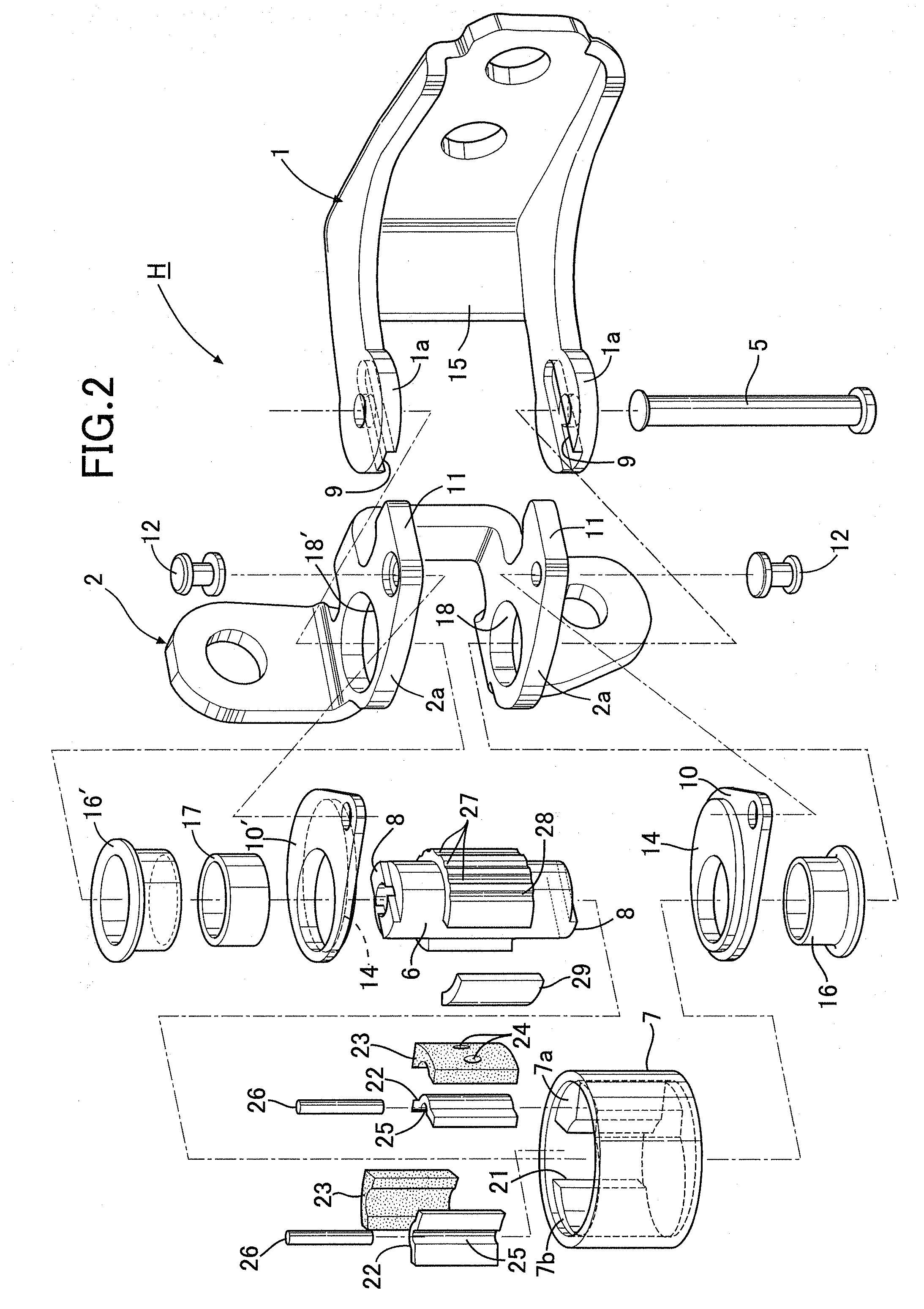
[0027]As shown in FIGS. 2 to 5, the door hinge device H includes: a female bracket 1 fixed to the body B with a plurality of bolts 3; a male bracket 2 fixed to the door D with a plurality of bolts 4; and a hinge pin 5 disposed in a vertical direction to couple these brackets 1 and 2 in a relatively rotatable manner.

[0028]The female bracket 1 includes a pair of upper and lower female arm portions 1a. A pair of upper and lower male arm portions 2a of the male bracket 2 are arranged adjacently on the inner sides of the upper and lower female arm portions 1a, respectively. The hinge pin 5 is arranged to vertically penetrate the arm portions 1a and 2a. The hinge pin 5 is fixed to the female arm portions 1a by an enlarged head portion 5a on o...

second embodiment

[0056]Next, the present invention, which is shown in FIG. 10, will be described.

[0057]In the second embodiment, each of the holding members 22 provided respectively in the attachment concave portions 21 in the outer cylinder 7 is formed of a plate spring, and includes a pair of end wall portions 22a and a flexible connecting wall portion 22b. The end wall portions 22a are placed respectively on the inner walls, facing each other in the circumferential direction of the outer cylinder 7, of the attachment concave portion 21, while the connecting wall portion 22b integrally connect the end wall portions 22a to each other. A holding groove 25 for holding the detent roller 26 is formed in the connecting wall portion 22b, while the elastic member 23 made of rubber is filled in the attachment concave portion 21 so as to urge the connecting wall portion 22b towards the inner cylinder 6. Since the other configurations in the second embodiment are the same as those of the aforementioned embod...

third embodiment

[0059]Lastly, the present invention, which is shown in FIG. 11, will be described.

[0060]The third embodiment shows that a semi-columnar detent projection 26 extending in the axial direction of the outer cylinder 7 may be formed integrally on each holding member 22 in place of the detent roller 26 in each of the first and second embodiments. FIG. 11 shows a representative example of the third embodiment, in which the holding members 22 and the detent roller 26 in the first embodiment shown in FIG. 5 are modified. Since the other configurations in the third embodiment are the same as those of the first embodiment, parts corresponding to those in the first embodiment will be denoted by the same reference numerals in FIG. 11, and overlapping descriptions therefor will be omitted.

[0061]According to the third embodiment, the forming of the detent projection 26 integrally on each holding member 22 makes it possible to simplify the structure by reducing the number of components, and further...


PUM


Abstract

A checker-equipped door hinge device for vehicle includes: a first bracket fixed to one of a body and a door; a second bracket fixed to another one of the body and the door; a hinge pin connecting the first and second brackets to each other, and allowing the brackets to be relatively rotatable; an inner cylinder connected integrally to the first bracket and disposed coaxially with the hinge pin; an outer cylinder connected integrally to the second bracket and disposed so as to surround the inner cylinder in a manner of being rotatable relative to the inner cylinder; and a checking-force generating mechanism provided between the inner cylinder and the outer cylinder, the checking-force generating mechanism generating a checking force against the door at a predetermined opening position of the door, wherein an inner peripheral surface and an outer peripheral surface of the outer cylinder are eccentric to each other, so that a thick wall portion having a large distance between the inner peripheral surface and the outer peripheral surface is formed in the outer cylinder, and the checking-force generating mechanism is provided in the thick wall portion. Thereby the door hinge device can be compact, in which the checking-force generating mechanism can be disposed in the outer cylinder without increasing the diameter of the outer cylinder.

Description

CROSS REFERENCE TO RELATED APPLICATION[0001]This application claims the priority of Japanese Application No. 2007-190019, filed Jul. 20, 2007, the entire specification, claims and drawings of which are incorporated herewith by reference.BACKGROUND OF THE INVENTION[0002]1. Field of the Invention[0003]The present invention relates to a vehicle door hinge device that supports a door for opening and closing a door opening or a tail gate of an automobile or the like, specifically, a checker-equipped door hinge device for vehicle, comprising: a first bracket fixed to one of a body and a door; a second bracket fixed to another one of the body and the door; a hinge pin connecting the first and second brackets to each other, and allowing the brackets to be relatively rotatable; an inner cylinder connected integrally to the first bracket and disposed coaxially with the hinge pin; an outer cylinder connected integrally to the second bracket and disposed so as to surround the inner cylinder in ...

Claims


Application Information

Patent Timeline
Patent Type & Authority Patents(United States)
IPC IPC(8): E05D11/10
CPCE05D11/1057E05Y2900/531Y10T16/61Y10T16/54056Y10T16/54038Y10T16/54028
Inventor OCHIAI, MANABU
Owner RIKEN KAKI KOGYO CO LTD
Why Eureka
Try Eureka