Illuminant system using high color temperature light emitting diode and manufacture method thereof

a technology of light-emitting diodes and illuminant systems, which is applied in the direction of discharge tubes, luminescnet screens, instruments, etc., can solve the problems of difficult to meet design standards, the difficulty of using white lights of low color temperature as the light source of the backlight module, and the inability to increase the color temperature of the light without significantly increasing the cost, etc., to achieve the effect of higher color temperatur

Active Publication Date: 2012-02-07
OPTRONIC SCI LLC
View PDF4 Cites 54 Cited by
  • Summary
  • Abstract
  • Description
  • Claims
  • Application Information

AI Technical Summary

Benefits of technology

[0008]An object of this invention is to provide a light emitting diode illuminant system and a manufacture method thereof, which is capable of outputting lights of higher color temperature.
[0009]Another object of this invention is to provide a light emitting diode illuminant system and a manufacture method thereof, which can output required light performances while controlling the manufacturing cost.
[0010]Another object of this invention is to provide a backlight module capable of outputting lights of higher color temperature.

Problems solved by technology

However, for a larger liquid crystal display, particularly for a liquid crystal television panel, due to the high color temperature requirement of the industrial standards, using white lights of low color temperature as the light source of the backlight module is difficult to meet the design standards.
In order to solve the problem, how to increase the color temperature of the light without significantly increasing the cost has become one major issue.

Method used


Image

  • Illuminant system using high color temperature light emitting diode and manufacture method thereof
  • Illuminant system using high color temperature light emitting diode and manufacture method thereof
  • Illuminant system using high color temperature light emitting diode and manufacture method thereof

Examples


first embodiment

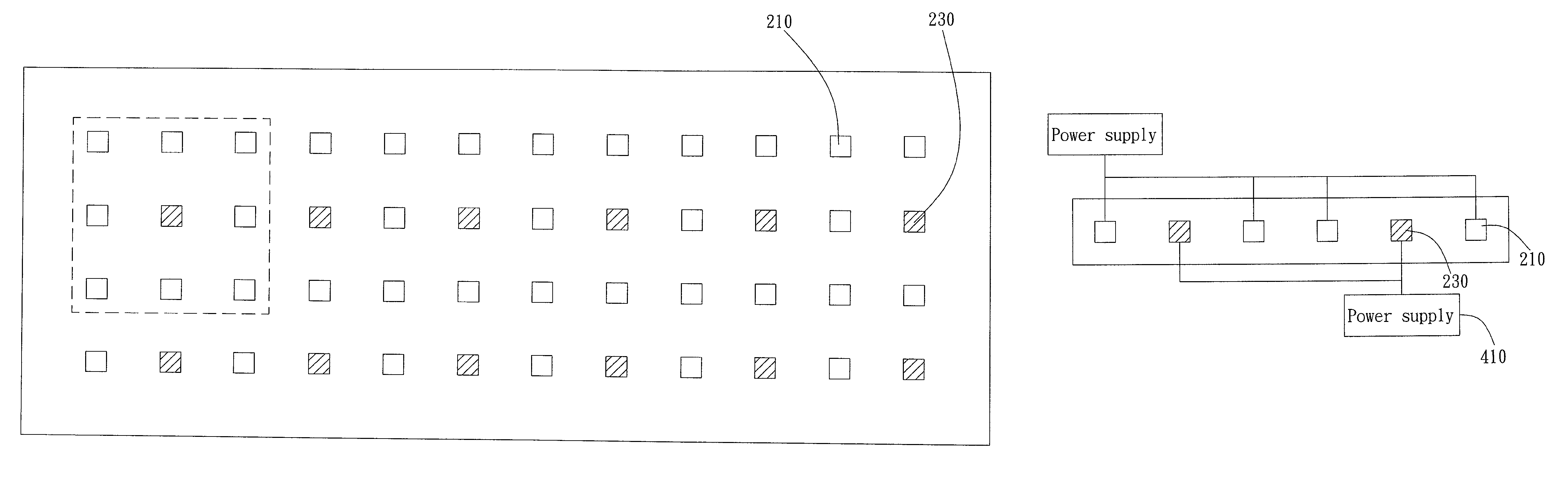
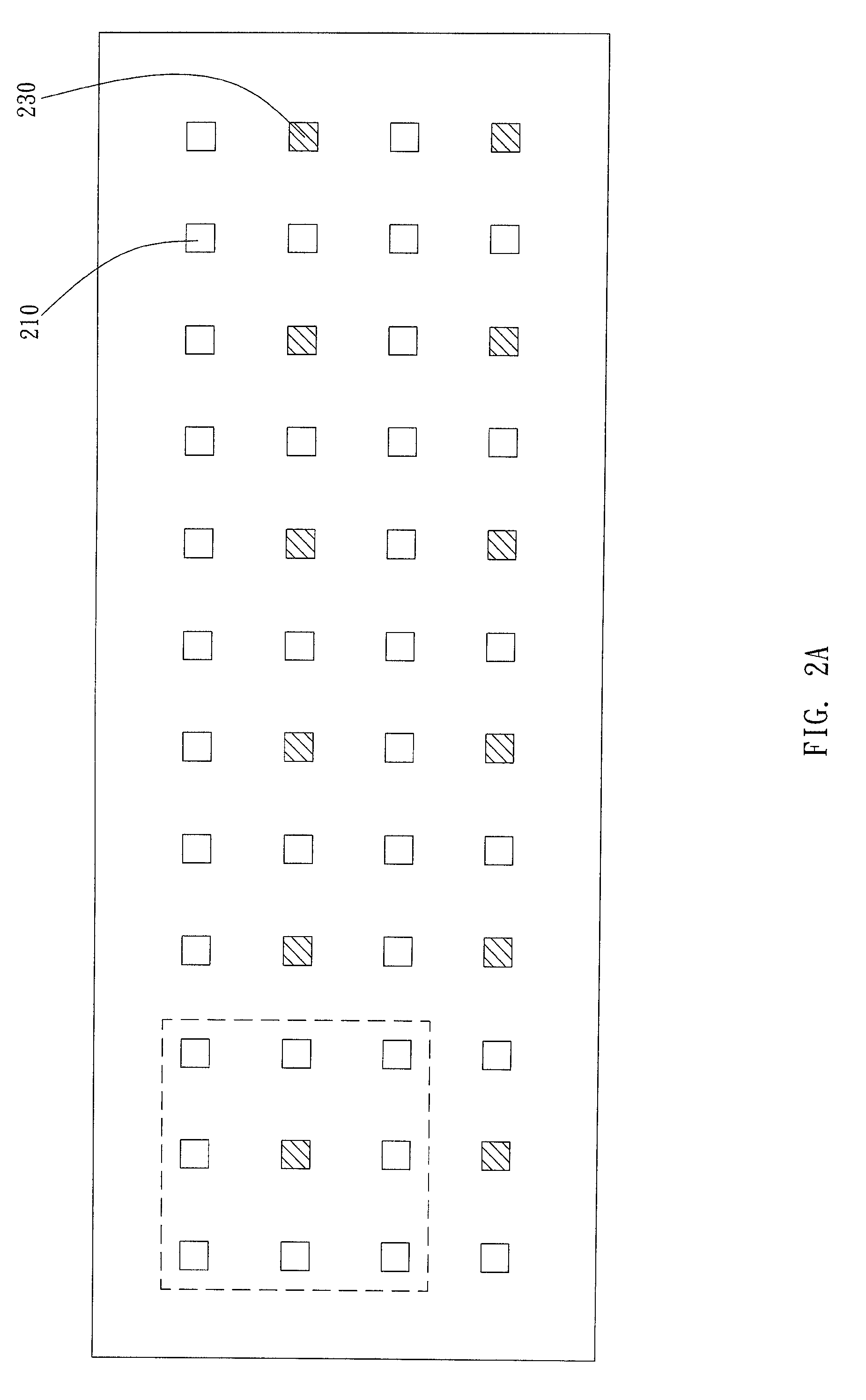
[0029]FIG. 2A illustrates a LED illuminant system. In this embodiment, the LED illuminant system is an array consisting of a plurality of LEDs. The white light illuminant is a white LED 210, and the green light illuminant is a green LED 230. Each green LED 230 is disposed adjacent to the white LED 210 and surrounded by the white LEDs 210. As illustrated in FIG. 2A, the LEDs in the first row and the third row are all white LEDs 210, while the LEDs in the second row and the fourth row are the white LEDs 210 and the green LEDs 230 arranged alternatively. In other words, each green LED 230 is surrounded by the white LEDs 210. More particularly, for example, in a 3×3 matrix, for the green LED 230 disposed at the second column and the second row (2, 2), the LEDs proximate to the green LED 230 are all white LEDs 210; that is the green LED 230 is only proximate to white LEDs 210. For some white LEDs 210 in the drawing (i.e. in the second row or the fourth row), one green LED 230 is disposed...

second embodiment

[0032]FIG. 6A illustrates a LED illuminant system. In this embodiment, the LED illuminant system is a single LED. The LED includes a package unit 510, a blue light chip 530, and a prism 550. The blue light chip 530 is disposed in the package unit 510. The prism 550 covers the blue light chip 530 and fills in the cavity of the package unit 510. In the embodiment of FIG. 6A, the package unit 510 is a holder with a recessed cavity. Therefore, the prism 550 can be disposed in the cavity. However, in another embodiment, as illustrated in FIG. 6B, the package unit 510 can be a substrate and the prism 550 encapsulates the blue light chip 530 on the package unit 510.

[0033]In the embodiment illustrated in FIG. 6A, the yellow phosphors 571 of the LEDs are provided in the prism 550 in a mix distribution manner and serve as the white light illuminant. When the blue light chip 530 illuminates, the light can excite the yellow phosphors 571 to emit white light. Preferably, the yellow phosphors 571...


PUM


Abstract

A light emitting diode (LED) illuminant system, a manufacture method thereof, and a backlight module using the same are provided. The LED illuminant system includes a plurality of white light illuminants and at least one green light illuminant mixed in the white light illuminants. A light power ratio of the green light illuminant to the white light illuminants is in between ⅕ to 1 / 20. The color temperature of the whole illuminant system will be enhanced to a certain extent by mixing the green light illuminant and the white light illuminants. The manufacture method includes the following steps: obtaining a transmission spectrum of the white light illuminants; analyzing the transmission spectrum to determine n supplemental amount of a green light; and disposing at least one green illuminant in accordance with the supplemental amount of the green light.

Description

[0001]This application claims the priority based on a Taiwanese Patent Application No. 097118682, filed on May 21, 2008, the disclosure of which is incorporated herein by reference in its entirety.BACKGROUND OF THE INVENTION[0002]1. Field of the Invention[0003]This invention relates to a light emitting diode (LED) illuminant system, a manufacture method thereof, and a backlight module using the same; more particularly, this invention relates to a light emitting diode illuminant system having high color temperature and a manufacture method thereof.[0004]2. Description of the Prior Art[0005]Display panels and panel display devices using the display panels have become the mainstream of various display devices. For example, various panel displays, home flat televisions, panel monitors of personal computers and laptop computers, and display screens of mobile phones and cameras are products widely using display panels. Particularly, the market demand for liquid crystal display devices lar...

Claims


Application Information

Patent Timeline
Patent Type & Authority Patents(United States)
IPC IPC(8): F21V9/00
CPCG02F1/133603G02F1/133609
Inventor CHANG, YA-HSIENLIN, HSIN-WU
Owner OPTRONIC SCI LLC
Why Eureka
Try Eureka