Light projecting apparatus of scanner module and method for arranging light sources thereof

a technology of light projecting apparatus and scanner module, which is applied in the direction of lighting and heating apparatus, lighting support devices, transportation and packaging, etc., can solve the problem of inability to improve the signal/noise ratio (s/n ratio), the brightness of the entire body is illuminated, and the brightness of the middle part is significant, so as to achieve optimal brightness uniformity, reduce image distortion caused by the firmware (f/m) process at the posterior end, and improve image scanning quality.

Active Publication Date: 2012-02-07
TECO IMAGE SYST
View PDF2 Cites 8 Cited by
  • Summary
  • Abstract
  • Description
  • Claims
  • Application Information

AI Technical Summary

Benefits of technology

[0013]The present disclosure with the various embodiments arranges the light emitting diodes by means of continuous unequal spacing intervals, thereby enabling optimal brightness uniformity. The image distortion caused from the firmware (F / M) process at the posterior end can be decreased substantially and the image scanning quality can be further increased after the image brightness has been made more uniform by means of the process of an imaging system (i.e. the S / N ratio at each one of the two ends is increased).

Problems solved by technology

However, the illumination brightness of the entire body has the same characteristic problem as the fluorescent tube, namely, there is a significant drop between the brightness of a middle part thereof and the brightness of the two ends thereof.
However, the manner mentioned above is unable to improve a signal / noise ratio (S / N ratio); the noise is also amplified after the brightness of the two ends is increased by means of the firmware (F / W), causing an image to be distorted.

Method used


Image

  • Light projecting apparatus of scanner module and method for arranging light sources thereof
  • Light projecting apparatus of scanner module and method for arranging light sources thereof
  • Light projecting apparatus of scanner module and method for arranging light sources thereof

Examples


Embodiment Construction

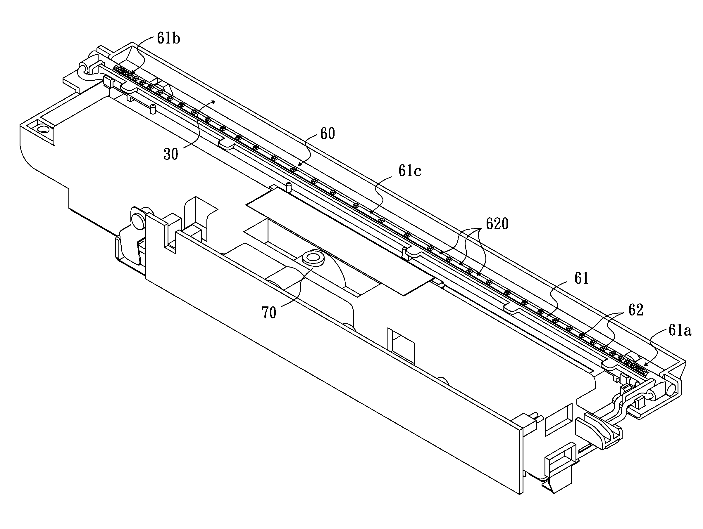
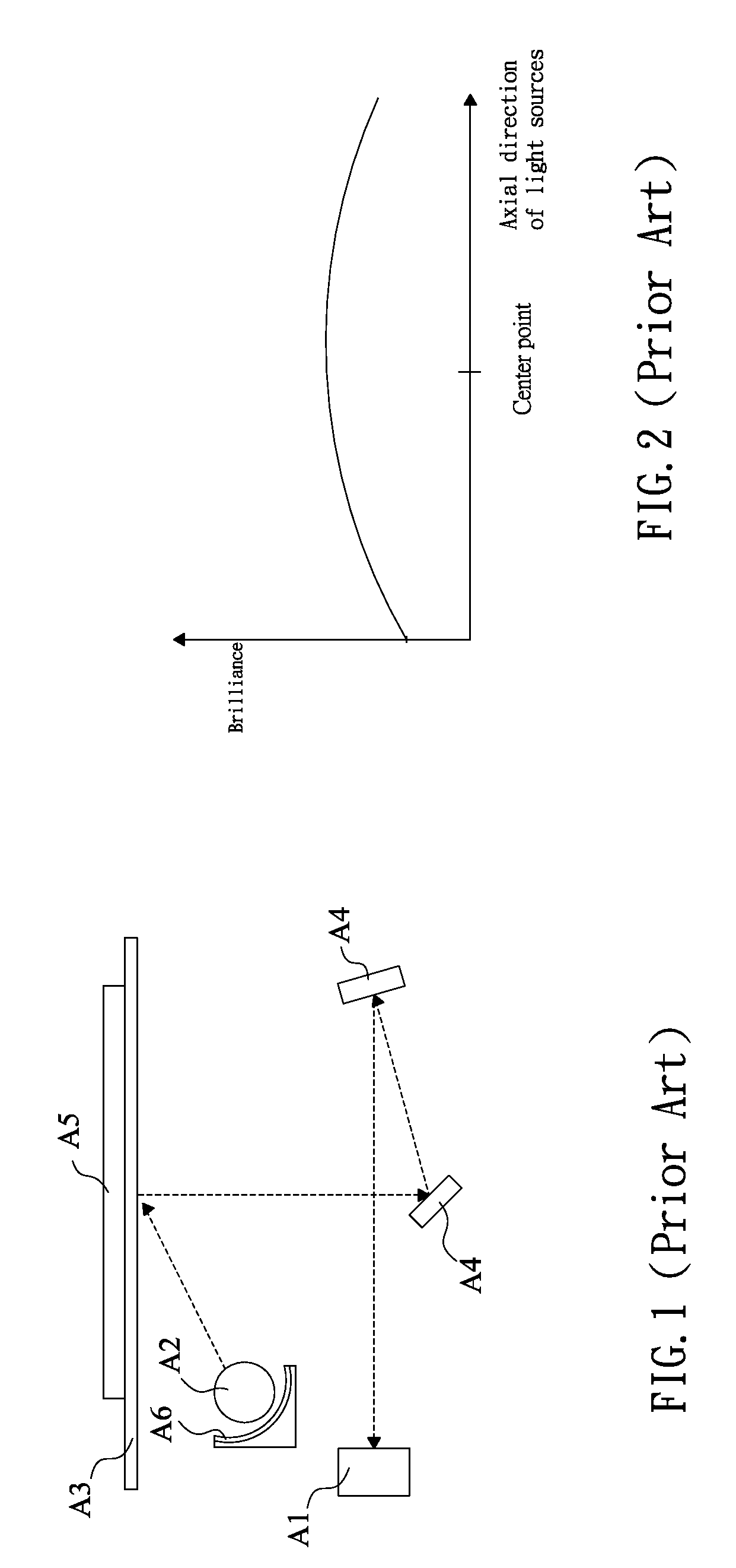
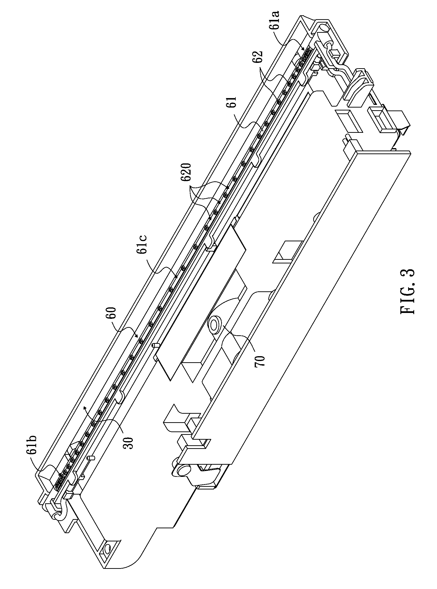
[0023]Please refer to FIGS. 3, 4, 5, 6A and 6B. FIG. 3 is a perspective view, showing a light projecting apparatus according to a first embodiment. FIG. 4 is a plane view, showing a light projecting apparatus according to another embodiment. FIG. 5 is a schematic view, showing a structure of a light projecting apparatus applied in a scanner module according to another embodiment. FIG. 6A is a diagram, showing a brightness curve of a general light projecting apparatus according to another embodiment. FIG. 6B is a diagram of a brightness curve, showing an LED light projecting apparatus according to another embodiment.

[0024]A light projecting apparatus 60 of a scanner module includes a substrate 61 and multiple light emitting diodes (LEDs) 62.

[0025]The substrate 61 has approximately a long strip shape, and includes a first end 61a, a second end 61b and a middle section 61c. The first end 61a and the second end 61b are respectively positioned at two sides of the middle section 61c, in w...


PUM


Abstract

A light projecting apparatus of a scanner module and a method for arranging the light sources thereof are provided. The light projecting module includes a substrate with a first end, a second end and a middle section. The first end and the second end are respectively positioned at both sides of the middle section. The light projecting module also includes multiple light emitting diodes (LEDs) positioned on the substrate. An arrangement spacing interval is formed between every two adjacent light emitting diodes; the arrangement spacing intervals are respectively decreased gradually from the middle section toward both the first end and the second end.

Description

CROSS-REFERENCES TO RELATED APPLICATIONS[0001]This non-provisional application claims priority under 35 U.S.C. §119(a) on Patent Application No(s). 97122250 filed in Taiwan, R.O.C. on 2008 Jun. 13, the entire contents of which are hereby incorporated by reference.FIELD OF THE INVENTION[0002]The present invention relates to a light projecting apparatus and a method for arranging light sources thereof, and more particularly to a light projecting apparatus of a scanner module and a method for arranging light sources thereof.BACKGROUND[0003]Accompanying the progress of technology, optical scanners have already become a popular computer peripheral device. An image capturing method for an optical scanner mainly uses a light emitting device to project light onto a document. The light is guided to a light sensing element through a lens set after being reflected by the document, and the light sensing element can check and measure light with different strength reflected from different areas o...

Claims


Application Information

Patent Timeline
Patent Type & Authority Patents(United States)
IPC IPC(8): F21V33/00
CPCH04N1/02815H04N1/0285H04N1/0286H04N1/02865H04N1/02885H04N1/1013H04N1/193
Inventor CHEN, SAN-TANG
Owner TECO IMAGE SYST
Why Eureka
Try Eureka