Luminous flux depreciation notification system for light fixtures incorporating light emitting diode sources

a technology of light emitting diodes and luminous flux, which is applied in the field of light fixtures, can solve the problems of low light emitted, slow down of led output, and problems for users of led light fixtures

Inactive Publication Date: 2012-02-07
OLDENBURG GROUP
View PDF21 Cites 6 Cited by
  • Summary
  • Abstract
  • Description
  • Claims
  • Application Information

AI Technical Summary

Benefits of technology

[0013]The apparatus of the present disclosure is of a construction which is both durable and long lasting, and which will require little or no maintenance to be provided by the user throughout its operating lifetime. The apparatus of the present disclosure is also of inexpensive construction to enhance its market appeal and to thereby afford it the broadest possible market. Finally, all of the aforesaid advantages and objectives are achieved without incurring any substantial relative disadvantage.

Problems solved by technology

Unlike these sources, the output of an LED slowly declines over time, such that very little light is emitted from the LED by the time it reaches its thermal or mechanical limits.
This does, however, create a problem for users of LED light fixtures.
Unfortunately, such maintenance relies on diligent adherence to a maintenance schedule.
This creates a problem for lighting fixtures using LED light sources, which do not have a normal complete failure mode (provided that the LED light sources are operated within manufacturer's guidelines).
If the user of a space does not follow the recommended schedule for replacement of the LED light sources (replacement after a certain period of time equivalent to L70 life), the sources may fade to a point that the lighting is inappropriate long before the LED light sources fail completely and are changed.
Such a situation can cause, among other outcomes, reduced productivity, occupant discomfort, injury, and even death (in certain circumstances) when the lighting becomes too dim for its intended use.
[Though the practice of using a light-sensitive element (light sensor) to detect the amount of light emitted from a lighting system is not a new concept, the form factor and manufacturing means required for the construction of an LED lighting fixture creates difficulty in placement of the light sensitive element.
Further difficulty is introduced by the fact that most light fixtures operate in a space where there are other light-emitting elements, thus possibly contributing to the amount of light measured by an internal light sensor and introducing error into any intended measurement of the luminous flux produced by a light fixture.

Method used


Image

  • Luminous flux depreciation notification system for light fixtures incorporating light emitting diode sources
  • Luminous flux depreciation notification system for light fixtures incorporating light emitting diode sources
  • Luminous flux depreciation notification system for light fixtures incorporating light emitting diode sources

Examples


Embodiment Construction

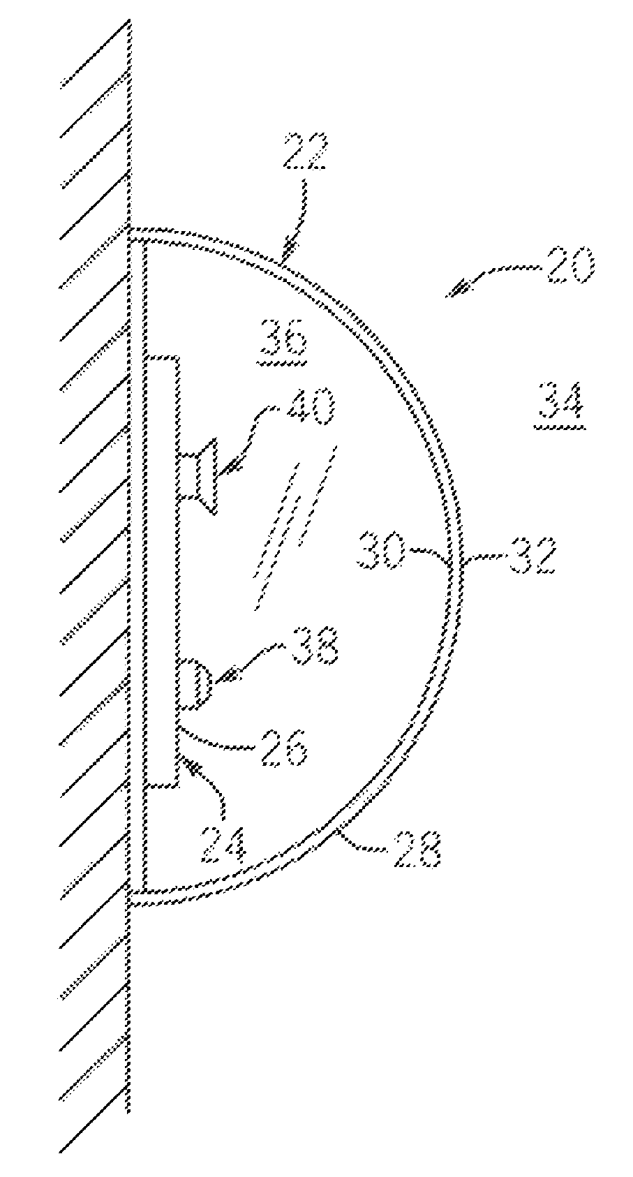
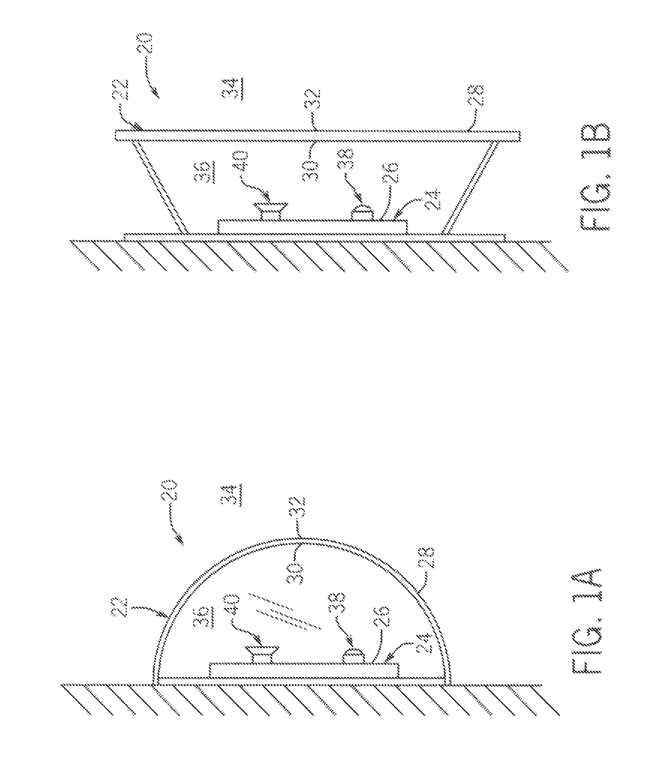
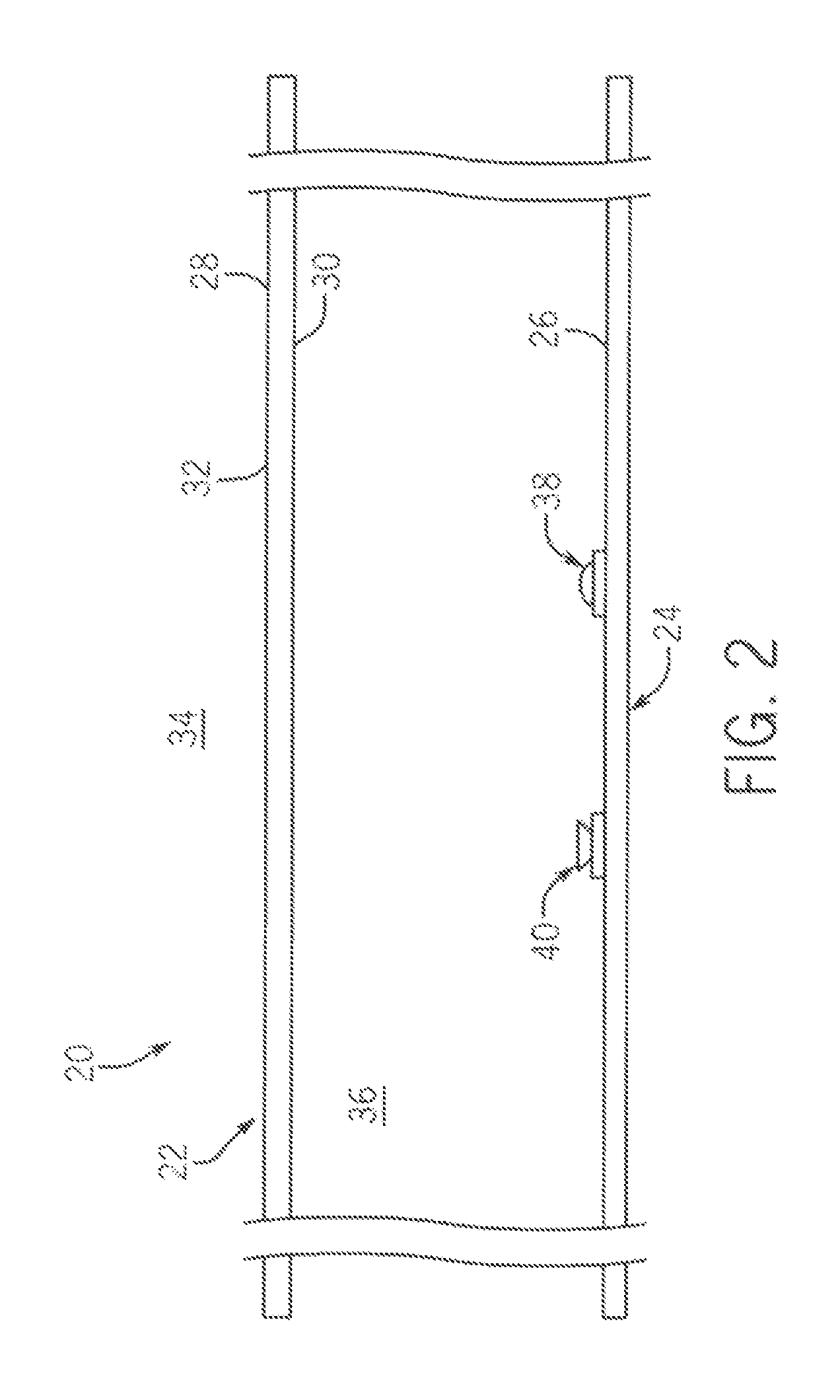
[0027]The disclosure includes two main parts. The first part is a light fixture 20 including an arrangement of components within an LED lighting fixture 20, heretofore identified as the optical arrangement. The second part is a luminous flux monitoring system 18 including a control and measurement system and control process integral to the control system that oversees its function. The embodiments described comprise preferred embodiments, but do not exclude other possible arrangements or systems achieving the same result through similar means that may be inferred from this disclosure.

[0028]For purposes of this disclosure, “light” is defined as that part of the electromagnetic spectrum having a wavelength or plurality of wavelengths between 360 nanometers and 800 nanometers, inclusive. Luminous flux (measured in lumens) is the sum of the radiant power (in Watts) of all wavelengths of light within a defined space, scaled to a standardized human visual response.

[0029]When light strikes...


PUM


Abstract

A LED light fixture and a luminous flux monitoring system for a light fixture. The light fixture includes a housing defining an interior space including an interior surface and a transmissive panel. A light source is coupled to the interior surface. The system includes a light sensor coupled to the interior surface and aligned to receive light from the transmissive panel, light source, and / or interior surface. The light sensor is configured to measure luminous flux in the interior space. A controller is coupled to the light source and the light sensor. The controller is configured to determine if a light sensor measurement of luminous flux in the interior space is more or less than a reference value of the luminous flux. If the measurement of luminous flux is less than the reference value, the controller is configured to activate an end-of-life indicator. The reference value equals (total flux−internal ambient flux)×depreciation factor.

Description

BACKGROUNDField of the Invention[0001]The present invention relates generally to light fixtures and more particularly to a monitor of the luminous flux of the light fixture.[0002]Lighting fixtures using light emitting diodes as a light source offer many potential benefits, including energy savings, reduction of hazardous substance waste, and greater convenience through reduced maintenance and replacement due to the greatly extended life compared to lighting fixtures using traditional light sources.[0003]Light emitting diodes (or LEDs) do not fail in the same manner as other common sources of light. Incandescent, fluorescent, and high-intensity discharge sources are generally assumed to be at the end of their lives when they “go out,” or fail. Unlike these sources, the output of an LED slowly declines over time, such that very little light is emitted from the LED by the time it reaches its thermal or mechanical limits. Provided the mechanical, thermal, and electrical support systems ...

Claims


Application Information

Patent Timeline
Patent Type & Authority Patents(United States)
IPC IPC(8): G01J1/42H05B37/02F21V23/04
CPCG01J1/18G01J2001/4252
Inventor GLANDT, CHRISTOPHER M.EISSNER, JAY M.HASTINGS, MARK J.
Owner OLDENBURG GROUP
Why Eureka
Try Eureka