Microphone with pressure relief

a pressure relief and microphone technology, applied in the field of microphones, can solve the problems of unusable microphones, more prone to breakage of microphones, and drum-like diaphragm approaches that may not be desirable configurations for other design reasons, and achieve the effect of increasing the dimension

Active Publication Date: 2012-02-07
INVENSENSE
View PDF4 Cites 27 Cited by
  • Summary
  • Abstract
  • Description
  • Claims
  • Application Information

AI Technical Summary

Benefits of technology

[0010]In one embodiment, the microphone chip includes a diaphragm that includes a first surface and at least one side. The diaphragm may be formed from polysilicon. The microphone chip includes a stationary portion having at least one side. The stationary portion may be part of a silicon substrate. Additionally, the microphone chip includes a plurality of springs coupled to the diaphragm and the stationary portion wherein a gap having a dimension exists between the side of the stationary portion and the side of the diaphragm. Additionally, the springs may extend increasing the dimension under a force presented by an audio input signal to the first surface of the diaphragm. The springs extend in a direction that is substantially perpendicular to the first side of the diaphragm. The microphone chip may also include a back plate that forms a capacitor with the diaphragm. The back plate may be formed from single crystal silicon. The capacitor creates an electrical output signal in response to an audio input signal. The back plate may have one or more holes that allow the audible input signal to pass there through and contact the diaphragm.

Problems solved by technology

Unlike microphones having diaphragms connected to the stationary member in a drum-like manner, this type of microphone is more prone to breaking due to the stresses concentrated in the springs.
As a result, when subjected to relatively high force events, such as high mechanical and / or acoustic shock events (e.g., door slam or jet engine), one or more springs can break, thus rendering the microphone unusable.
Although it may be more robust, however, a drum-like diaphragm approach may not be a desirable configuration for other design reasons (e.g., sensitivity concerns).

Method used


Image

  • Microphone with pressure relief
  • Microphone with pressure relief
  • Microphone with pressure relief

Examples


Embodiment Construction

[0018]In illustrative embodiments of the invention, a microphone is configured so that its diaphragm remains intact when subjected to relatively high force events. To that end, a plurality of springs connecting the diaphragm to the substrate assist in forming an effective pressure relief valve that, during high force events, assists in relieving pressure within the microphone. Details of various embodiments are discussed below. Additionally, microphone maintains sensitivity while providing pressure relief for high force events.

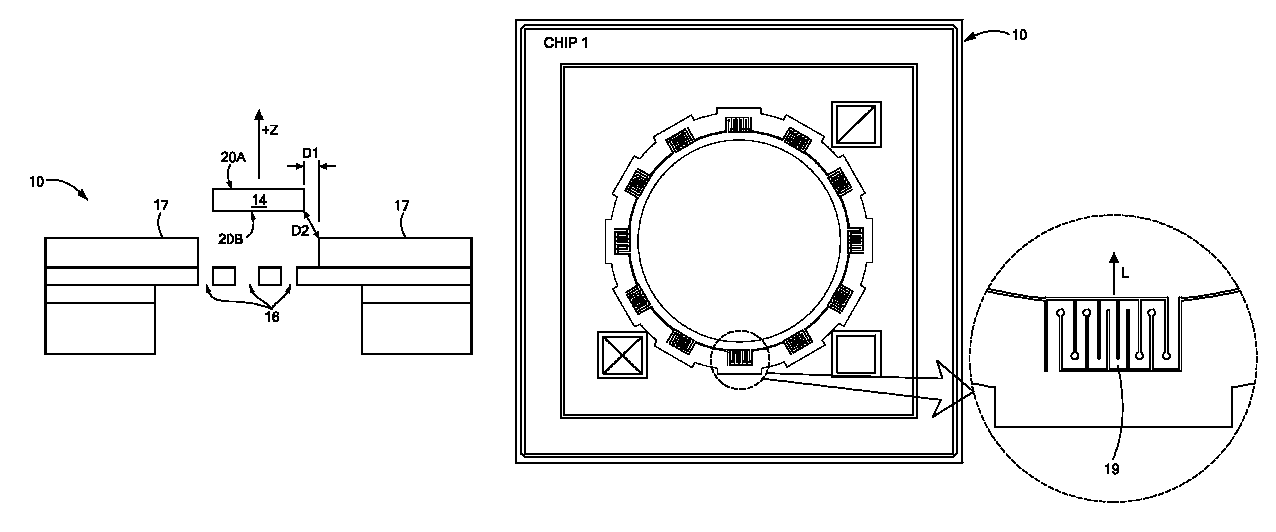
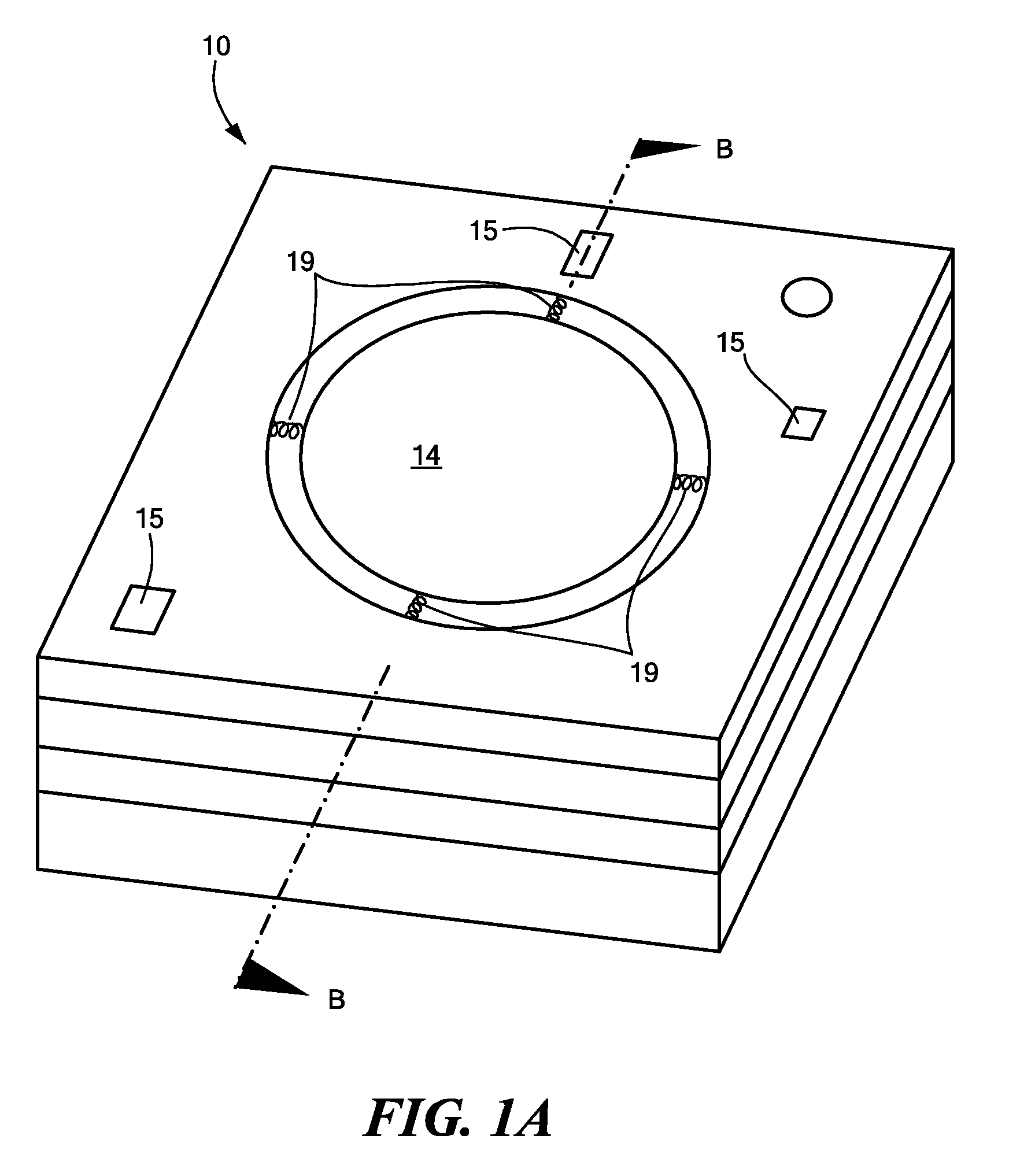
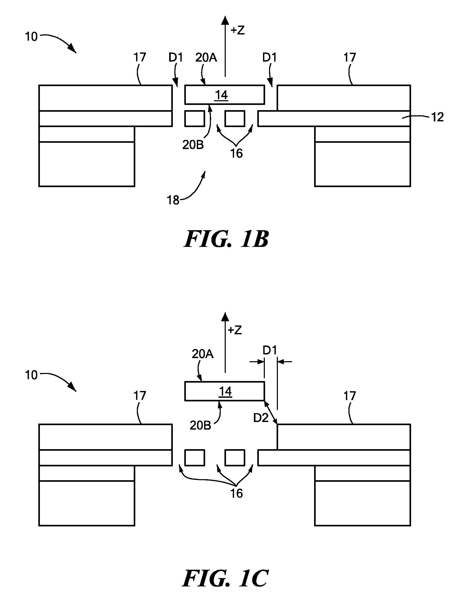
[0019]FIG. 1A schematically shows a top, perspective view of a microphone 10 (also referred to as a “microphone chip 10”) that may be fabricated in accordance with illustrative embodiments of the invention. FIG. 1B schematically shows a cross-section of the same microphone 10 across line B-B of FIG. 1A. Both FIGS. 1A and 1B show the microphone 10 when in the at rest position.

[0020]Among other things, the microphone 10 includes a static backplate 12 that suppor...


PUM

PropertyMeasurementUnit
diameteraaaaaaaaaa
diameteraaaaaaaaaa
distanceaaaaaaaaaa

Abstract

A microphone has a movable diaphragm having a rest position, a stationary portion, and a set of springs movably coupling the diaphragm and the stationary portion. The diaphragm and stationary portion are spaced a first distance when the diaphragm is in the rest position. When not in the rest position, however, the diaphragm and stationary portion are capable of being spaced a second distance, which is greater than the first distance. Despite the change in distance, the diaphragm still is capable of returning the space from the second distance to the first distance when the diaphragm returns to the rest position.

Description

CROSS-REFERENCE TO RELATED APPLICATIONS[0001]The present application claims priority from U.S. provisional patent application Ser. No. 60 / 885,314 filed on Jan. 17, 2007 the full disclosure of which is hereby incorporated herein by reference.FIELD OF THE INVENTION[0002]The invention generally relates to microphones and, more particularly, the invention relates to microphone diaphragm robustness.BACKGROUND OF THE INVENTION[0003]Many types of microphones have a diaphragm that forms a variable capacitor with a stationary member. During use, an incident audio signal causes the diaphragm to move relative to the stationary member. Consequently, this movement changes the capacitance of the variable capacitor to produce an electronic signal representing the incident audio signal. Eventually, this electronic signal may be processed to reproduce the incident audio signal on a speaker.[0004]Some microphones have a diaphragm that is movably connected with its underlying stationary member by mean...

Claims


Application Information

Patent Timeline
Patent Type & Authority Patents(United States)
IPC IPC(8): H04R11/02G01L9/00
CPCB81B3/0027H04R7/20H04R19/005B81B2201/0257H04R2307/207
Inventor ZHANG, XINJUDY, MICHAEL W.HARNEY, KIERAN P.WEIGOLD, JASON W.
Owner INVENSENSE
Why Eureka
Try Eureka