Multifuel internal combustion engine

a multi-fuel internal combustion engine technology, applied in the direction of combustion-air/fuel-air treatment, electric control, instruments, etc., can solve the problems of engine output performance and exhaust emission performance deterioration, tank breakage, etc., to suppress the deterioration of exhaust emission performance and drivability, and drive excellently

Active Publication Date: 2012-02-14
TOYOTA JIDOSHA KK
View PDF20 Cites 19 Cited by
  • Summary
  • Abstract
  • Description
  • Claims
  • Application Information

AI Technical Summary

Benefits of technology

[0017]In the multifuel internal combustion engine according to the present invention, even if the single low boiling point component fuel evaporated from the lubricant oil in the oil pan is supplied into the combustion chamber, the actual air / fuel ratio in the combustion chamber can be controlled to the target air / fuel ratio suitable for the driving condition. Therefore, according to this multifuel internal combustion engine, it is possible to suppress the deterioration in exhaust emission performance and drivability without being influenced by the evaporated single low boiling point component fuel, and the engine can be driven excellently in accordance with a driving condition.

Problems solved by technology

Therefore, if the pressure is not released outside, there is a possibility that the tank is broken.
However, for example, if gasoline fuel is evaporated, since harmful hydrocarbon (HC) component is included, such gas should not be released to the atmosphere in terms of environmental performance.
Therefore, an air / fuel ratio in the combustion chamber is deviated from a target air / fuel ratio at the time of purge control, and engine output performance and exhaust emission performance are deteriorated.

Method used


Image

  • Multifuel internal combustion engine
  • Multifuel internal combustion engine
  • Multifuel internal combustion engine

Examples


first embodiment

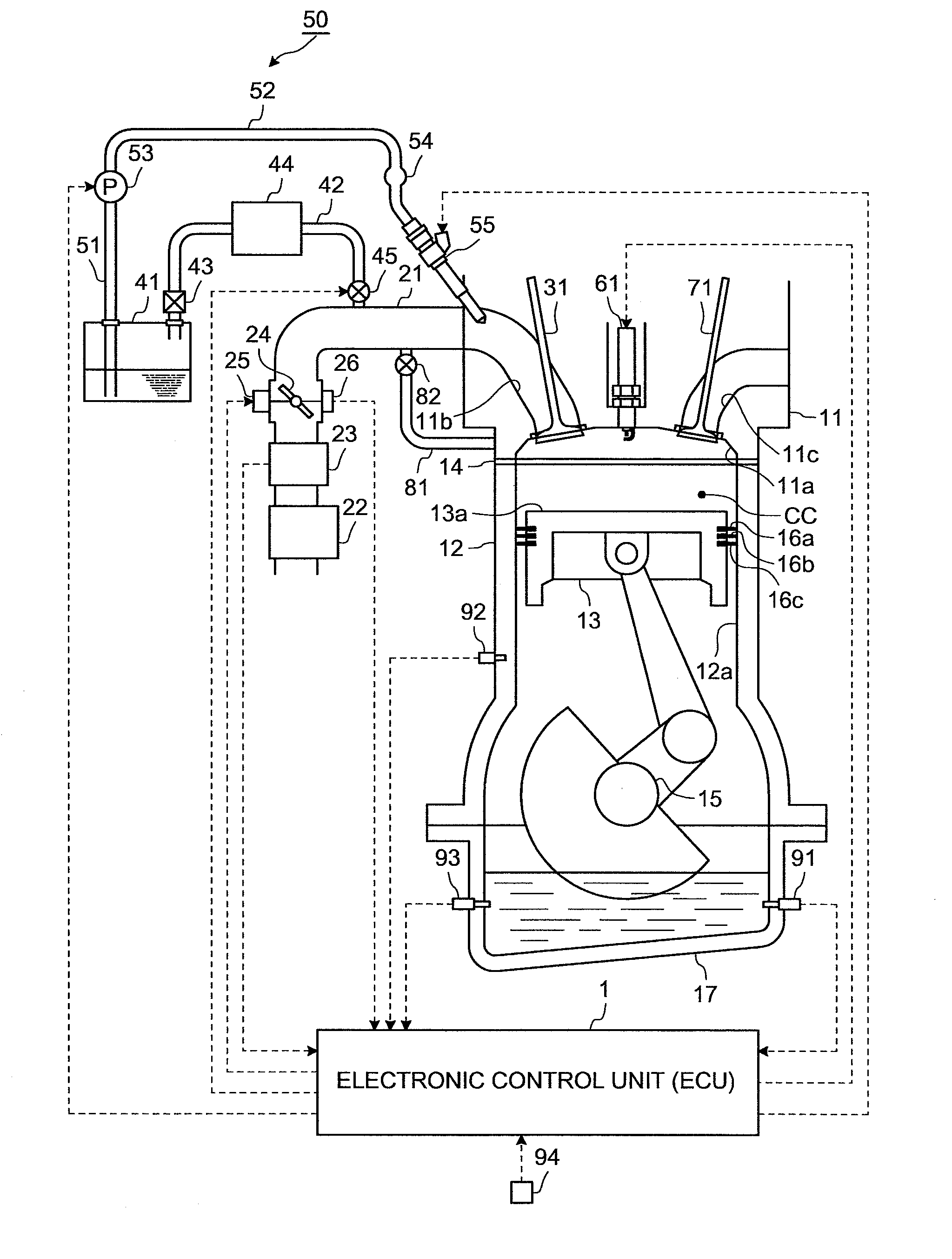
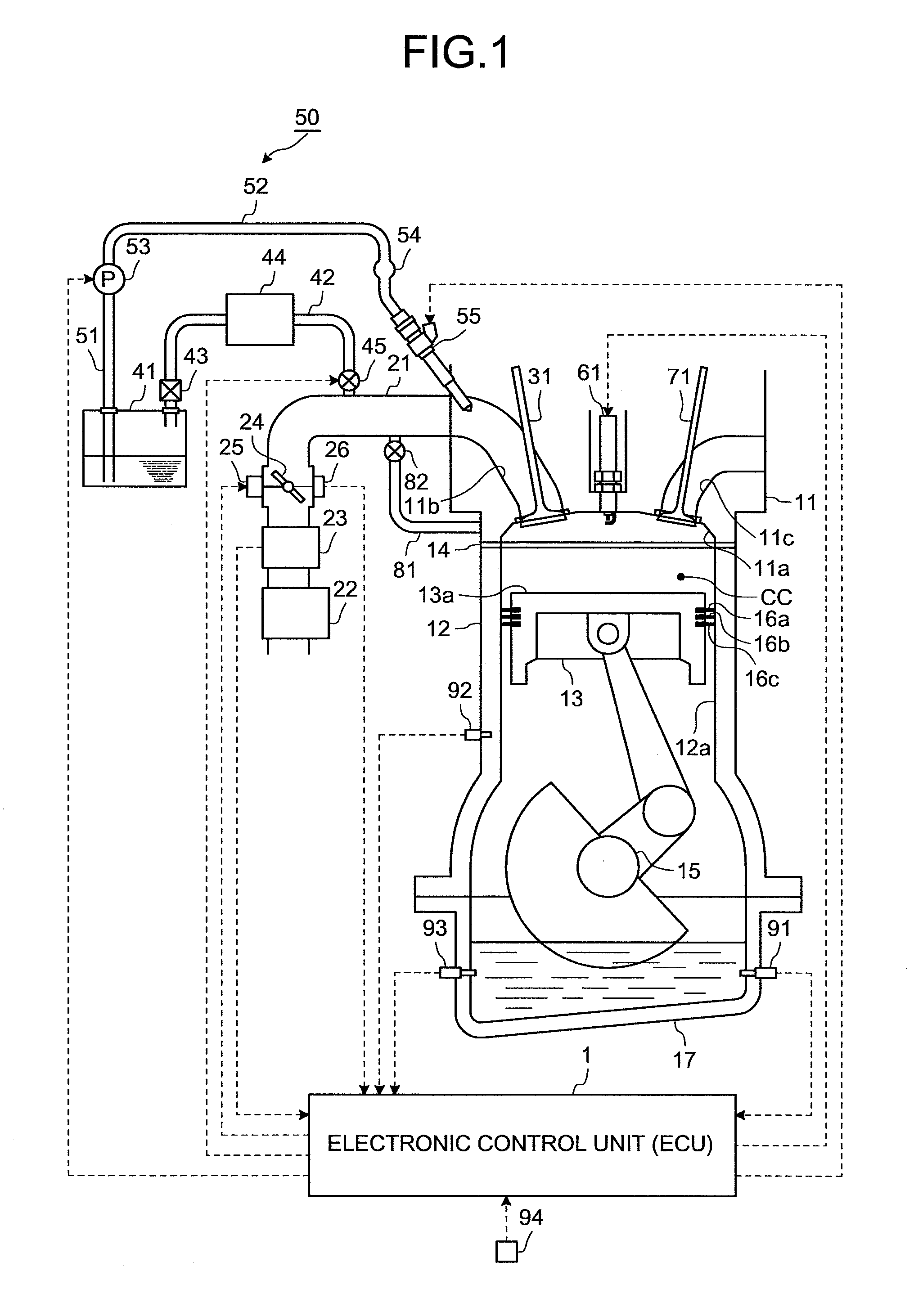
[0047]A first embodiment of the multifuel internal combustion engine according to the present invention will be explained based on FIGS. 1 to 3. In the multifuel internal combustion engine of the first embodiment, mixed fuel of single low boiling point component fuel and at least one kind of fuel having different properties from those of the single low boiling point component fuel is stored in one fuel tank, and the internal combustion engine is driven using the mixed fuel. Various control operations such as a fuel control and the like are executed by an electronic control unit (ECU) 1. The electronic control unit 1 includes a CUP (Central Processing Unit) (not shown), a ROM (Read Only Memory) in which a predetermined control program and the like are stored, a RAM (Random Access Memory) in which a calculation result of the CPU is temporarily stored, and a backup RAM in which previously prepared information and the like are stored. The single low boiling point component fuel is a sin...

second embodiment

[0080]A second embodiment of the multifuel internal combustion engine according to the present invention will be explained based on FIGS. 1 and 4.

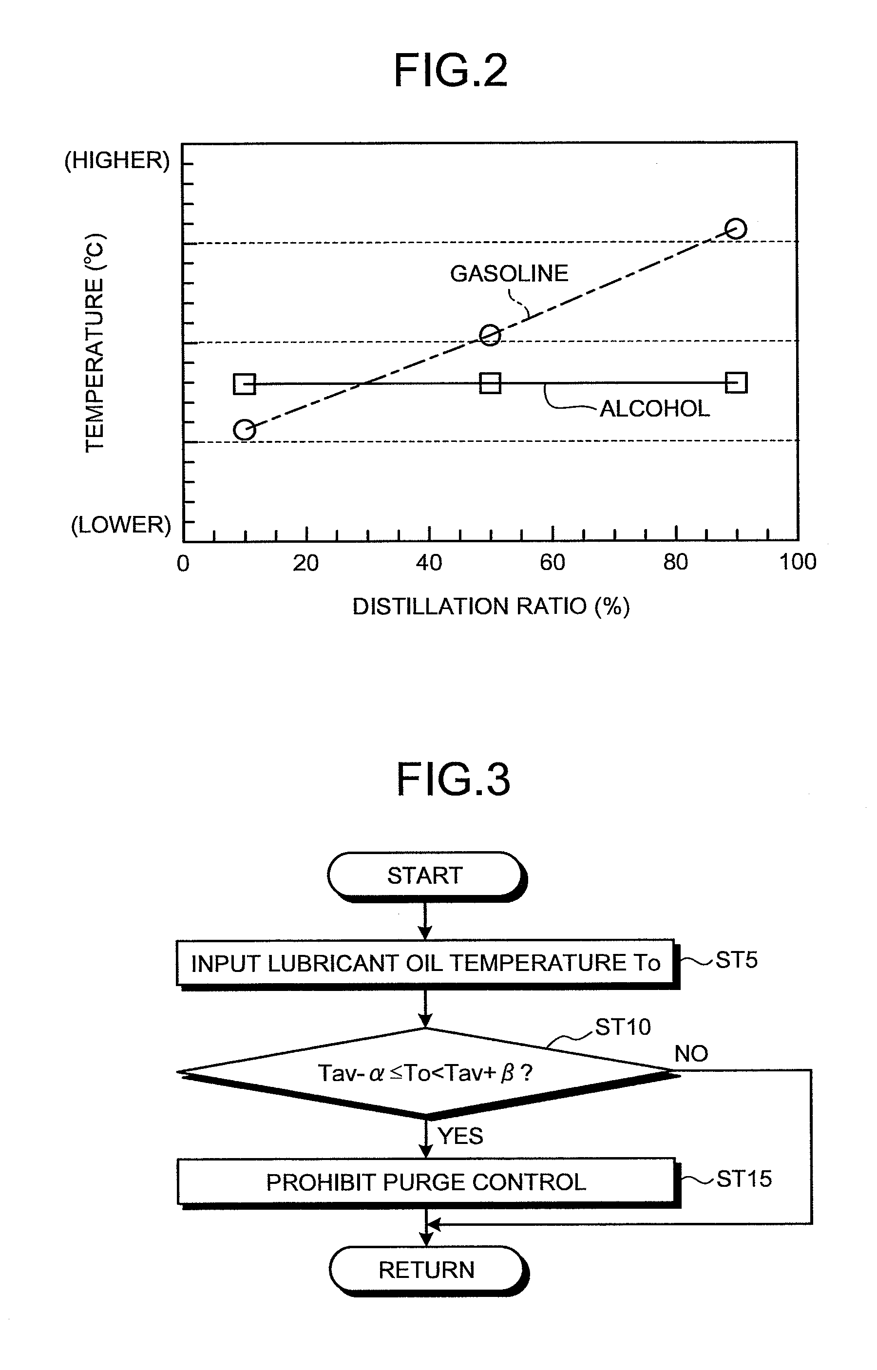
[0081]In the multifuel internal combustion engine of the first embodiment, if the temperature To of the lubricant oil in the oil pan 17 is within the purge control prohibiting temperature region (Tav−α≦To

[0082]However, the same amount of alcohol fuel (single low boiling point component fuel) is not always mixed in the lubricant oil in the oil pan 17 and it is not preferable to always prohibit the purge control only based on the temperature To of the lubricant oil. That is, when the amount of alcohol fuel mixed in the lubricant oil is small, the amount of alcohol fuel evaporated from the lubricant oil is also small. Therefore, if the purge control is not executed and evaporation gas is not supplied to the combustion chamber CC when high purge flow rate is required in the ...

third embodiment

[0098]Next, a third embodiment of the multifuel internal combustion engine according to the present invention will be explained based on FIGS. 1, 5 and 6.

[0099]The multifuel internal combustion engine of the third embodiment is a modification of the multifuel internal combustion engine of the second embodiment, a mixing amount of the single low boiling point component fuel (alcohol fuel) into lubricant oil in the oil pan 17 is taken into account, and it is determined whether the purge control should be prohibited.

[0100]More specifically, in the third embodiment, the detected or estimated lubricant-oil dilution ratio Ro is not compared with the predetermined value (predetermined dilution ratio) Ra, and the predetermined purge control prohibiting temperature region (Tav−α≦To

[0101]Here, the purge control means of the electro...


PUM


Abstract

A multifuel internal combustion engine in which single low boiling point component fuel and at least one kind of fuel having properties different from those of the single low boiling point component fuel are introduced into a combustion chamber CC separately or together thereby operating the multifuel internal combustion engine, includes lubricant-oil temperature detecting unit means (temperature sensor 91) that detects a temperature of lubricant oil, or lubricant-oil temperature estimating unit means that estimates the temperature, and purge control unit means (electronic control unit 1) that prohibits purge control by an evaporation gas purge apparatus (evaporation gas passage 42, check valve 43, canister 44, on-off valve 45) or reduces a purge flow rate of evaporation gas in the purge control, when the detected or estimated temperature of the lubricant oil is near a boiling point temperature of the single low boiling point component fuel at which it is necessary to reduce a fuel injection amount from a fuel injection valve to a predetermined amount or less to adjust an air / fuel ratio of the combustion chamber to a target air / fuel ratio.

Description

TECHNICAL FIELD[0001]The present invention relates to a multifuel internal combustion engine which is operated using single low boiling point component fuel such as alcohol fuel and at least one kind of fuel having different properties from those of the single low boiling point component fuel.BACKGROUND ART[0002]Usually, fuel stored in a fuel tank is evaporated and fuel evaporation gas is produced. Generally, the fuel tank is tightly closed, and an internal pressure is increased as the evaporation gas is increased. Therefore, if the pressure is not released outside, there is a possibility that the tank is broken. However, for example, if gasoline fuel is evaporated, since harmful hydrocarbon (HC) component is included, such gas should not be released to the atmosphere in terms of environmental performance. Hence, in a conventional internal combustion engine, there is prepared an evaporation gas purge apparatus in which the evaporation gas is adsorbed by activated carbon in a caniste...

Claims


Application Information

Patent Timeline
Patent Type & Authority Patents(United States)
IPC IPC(8): F02D41/14F02M33/02F02M7/00G06F19/00
CPCF02D41/0025F02D41/0032F02D19/084F02M25/06F02M25/089F02D41/047F02D2200/023Y02T10/36F02D2250/11Y02T10/30
Inventor TSUNOOKA, TAKASHIWATANABE, TAKASHIHOSOKAWA, YOHEI
Owner TOYOTA JIDOSHA KK
Why Eureka
Try Eureka