Stem-mounted tire inflation pressure regulator

a pressure regulator and tire technology, applied in the direction of valve operating means/releasing devices, functional valve types, transportation and packaging, etc., can solve the problems of reducing fuel economy, increasing stopping distance, and lowering hydroplaning speed, so as to prevent undesired air loss, prevent inflation, and protect the effect of the sam

Inactive Publication Date: 2012-02-14
FLOW RITE CONTROLS
View PDF42 Cites 12 Cited by
  • Summary
  • Abstract
  • Description
  • Claims
  • Application Information

AI Technical Summary

Benefits of technology

[0010]In a first aspect of the invention, the regulator accurately and positively cuts off flow of air into the tire when the preset pressure point is reached. For example, the regulator includes a two-position valve which is stable only in one of two positions. Consequently, the valve is either fully open or fully closed. The regulator therefore provides a highly precise cutoff at the preset pressure.
[0013]In a fourth aspect of the invention, the regulator includes its own cap, which protects the regulator and which can be easily removed by the operator for inflation. As disclosed, the regulator cap threads onto and off of the device in the manner of a standard valve stem cap. Further, the assembly includes an air-tight seal to prevent undesired loss of air when the cap is installed. Consequently, the cap maintains the same protective functions as the valve stem cap that it replaces. Specifically, it prevents debris from entering both the regulator and the tire valve stem. It offers a secondary seal in case the tire valve develops a leak.

Problems solved by technology

Under-inflated tires adversely affect vehicle handling, can lower hydroplaning speed, and increase stopping distance.
Under-inflation also increases the rolling resistance of tires, leading to reduced fuel economy, increased hydrocarbon and toxic chemical emissions, and reduced tire life due to an increase in tire wall temperature and increased tread wear.
On a national scale, these problems have a significant impact on safety, energy usage, the environment, and waste management.
Most defects are related to under-inflation.
Fuel inefficiency also adds to the world's growing carbon dioxide emissions problem.
Because of cost and technology limitations, some TPMS may only alert the driver when pressure drops 25 percent or more below the manufacturer's recommended pressure.
This could be over eight PSI, which many in the tire industry feel is an inadequate safety margin.
Other problems with TPMS include failure of the driver to respond to the warning light.
For example, it is possible that drivers may see the light come on when the tires are cold, but turn off after driving for a while which warms the tires and thereby raises the tire pressure.
Or they may believe that the TPMS is faulty, in which case they may simply ignore it.
While the benefits of maintaining proper tire pressure are well documented, drivers do not always take action in response to the warning light because inflating tires is an unpleasant, dirty, inconvenient, and time-consuming task.
Often the equipment needed to accurately inflate tires is not available when needed.
Without a pressure gauge, there is no way to reliably set pressure to the manufacturer's recommended level.
If the tire is warm, then it is difficult for the driver to determine how much air to add so that there will be adequate pressure when the tire is cold.
Although these systems are potentially available for automobile use, their relatively high cost and complexity have inhibited their widespread use by light vehicle manufacturers.

Method used


Image

  • Stem-mounted tire inflation pressure regulator
  • Stem-mounted tire inflation pressure regulator
  • Stem-mounted tire inflation pressure regulator

Examples


Embodiment Construction

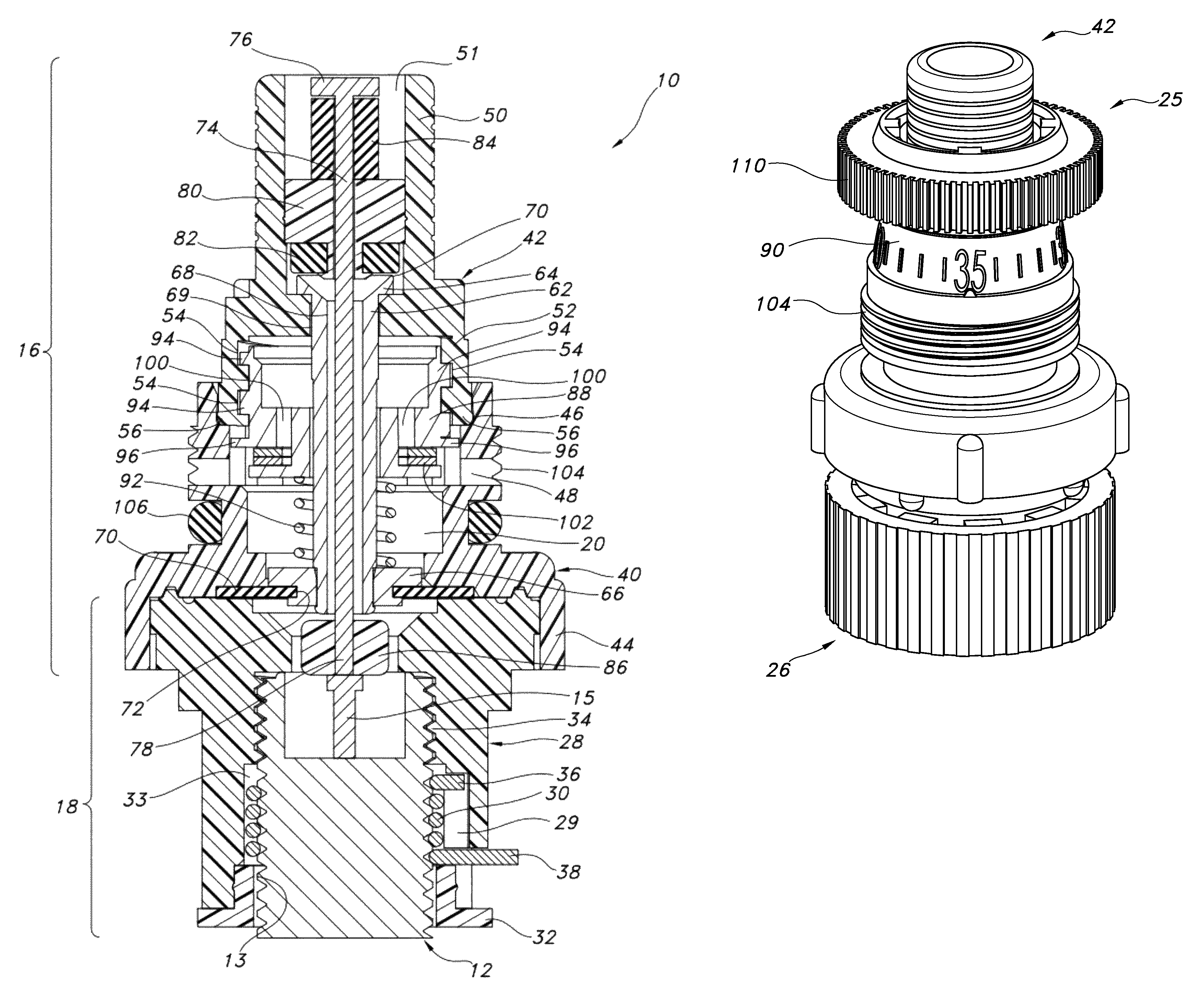
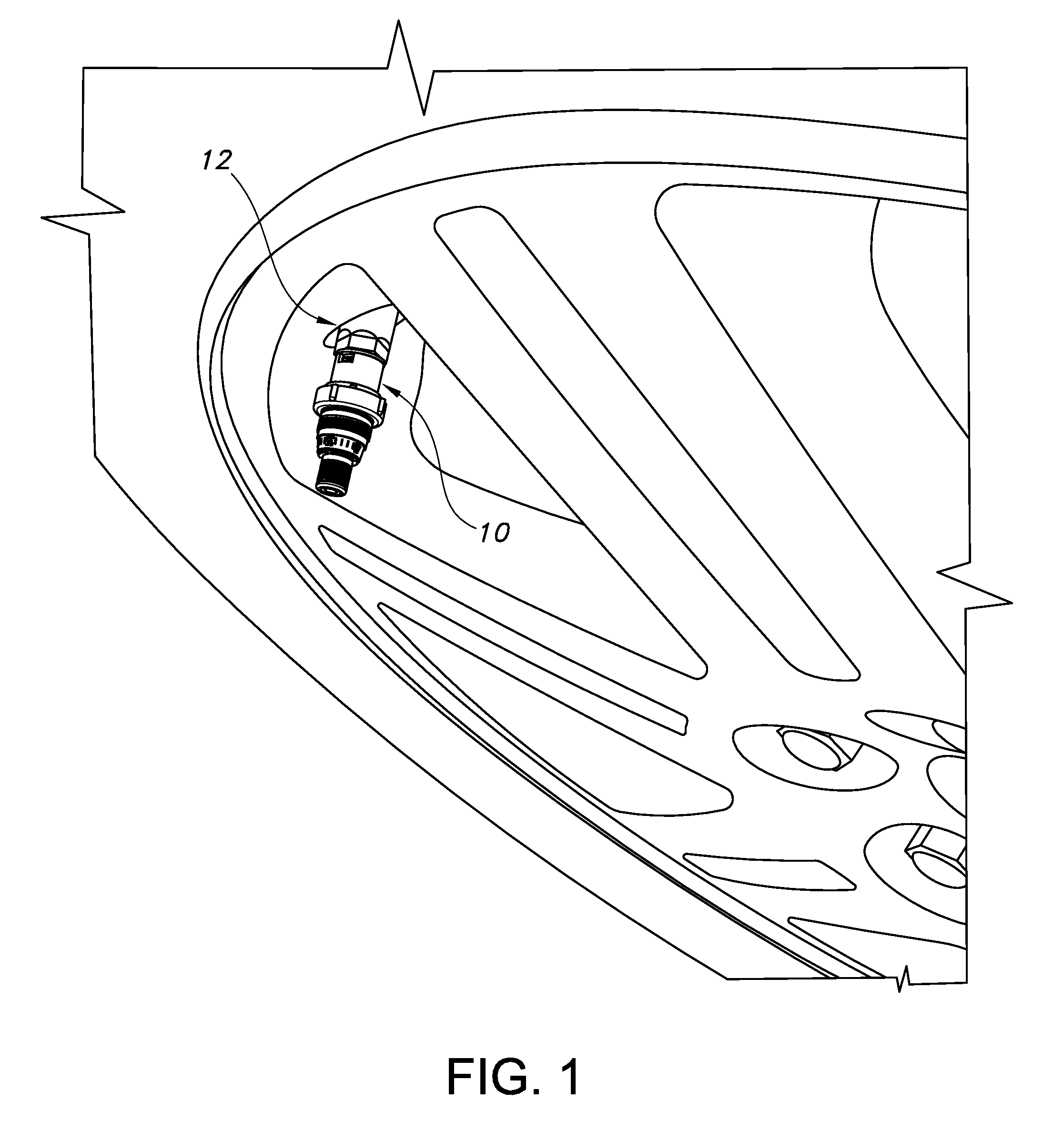
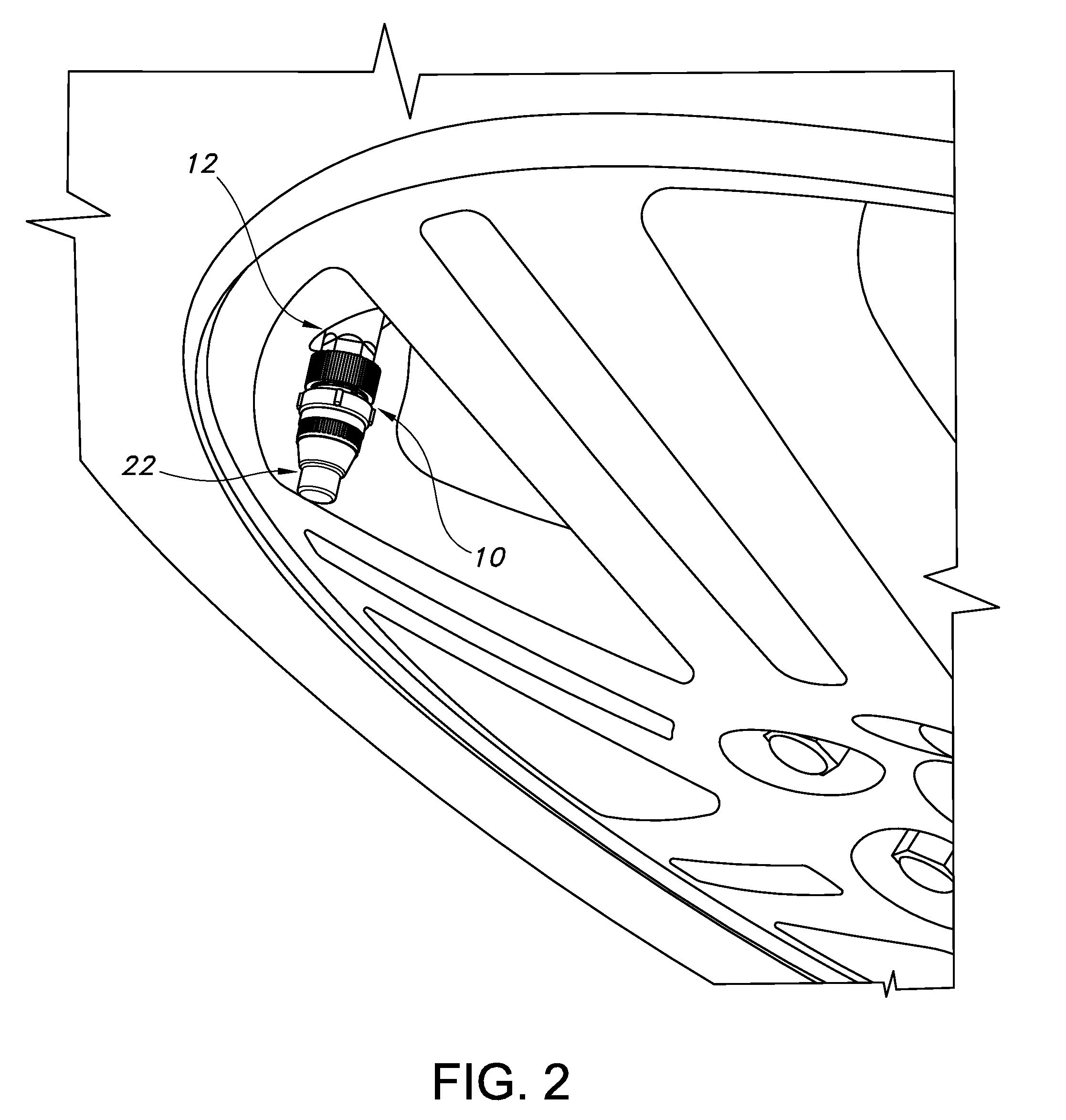
[0028]A stem-mounted tire inflation pressure regulator constructed in accordance with the current embodiment of the invention is illustrated in the drawings and generally designated 10. As illustrated in FIGS. 1-2 and 5-7, the regulator 10 is mounted on conventional tire stem 12 of a conventional wheel. The regulator 10 receives a conventional air nozzle 14 as illustrated in FIGS. 6-7 to permit filling of the vehicle tire. A valve assembly 20 within the regulator 10 permits air to flow from the air nozzle 14 to the valve stem 12 until a preset pressure is achieved within the tire. The valve assembly 20 then snaps closed to prevent further filling of the tire beyond the present pressure. After the valve is closed, air from the nozzle 14 is diverted through an audible device to provide an audible signal to the operator.

I. Regulator

[0029]As perhaps best illustrated in FIG. 5, the regulator 10 includes an upper assembly 16, a lower assembly 18, and a valve assembly 20. In addition to th...


PUM


Abstract

The specification discloses a tire inflation pressure regulator facilitating precise tire inflation. The regulator includes a body, a two-position valve within the body, and a rotational lock. The body includes an air inlet, an air outlet, and an air vent. In one position, the valve directs air from the air inlet to the air outlet when the tire pressure is below a preset level; and, in a second position, the valve directs air from the air inlet to the air vent when the tire pressure exceeds the preset level to prevent overfilling. The valve moves rapidly between the two positions, and is unstable between the two positions. The valve includes a regulator enabling the preset level to be adjusted. The rotational lock enables the regulator to be screwed onto a tire stem, but prevents removal of the regulator from the tire stem without a key. The regulator preferably includes a cap removably sealed over the air inlet and the air vent to prevent the undesired loss of air.

Description

BACKGROUND OF THE INVENTION[0001]The present invention relates to tire inflation pressure regulators, and more particularly to such regulators that can be installed or mounted directly on a conventional tire valve stem.[0002]A great deal of government and industry attention has been focused on the problems associated with under-inflated vehicle tires. Tires naturally lose air pressure because of permeation through the tire wall at the rate of about two pounds per square inch (PSI) per month. Under-inflated tires adversely affect vehicle handling, can lower hydroplaning speed, and increase stopping distance. Under-inflation also increases the rolling resistance of tires, leading to reduced fuel economy, increased hydrocarbon and toxic chemical emissions, and reduced tire life due to an increase in tire wall temperature and increased tread wear.[0003]On a national scale, these problems have a significant impact on safety, energy usage, the environment, and waste management. For exampl...

Claims


Application Information

Patent Timeline
Patent Type & Authority Patents(United States)
IPC IPC(8): F16K31/12
CPCB60C23/0496F16K15/207Y10T137/7808Y10T137/3646Y10T137/3755Y10T137/3631Y10T137/3662
Inventor CAMPAU, DANIEL N.
Owner FLOW RITE CONTROLS
Why Eureka
Try Eureka