Gas internal combustion type nailing machine

a gas internal combustion type and nailing machine technology, which is applied in the direction of nailing tools, positive displacement engines, reciprocating piston engines, etc., can solve the problems of degrading the combustion efficiency of mixed gas, increasing the operation load of the movable housing of the combustion chamber, and incomplete combustion of mixed gas, so as to enhance the ignition performance, reduce the gas flow speed in this portion, and increase the flow of mixed gas

Inactive Publication Date: 2012-02-14
MAX CO LTD
View PDF17 Cites 17 Cited by
  • Summary
  • Abstract
  • Description
  • Claims
  • Application Information

AI Technical Summary

Benefits of technology

[0006]One or more embodiments of the invention provide a gas internal combustion type nailing machine structured such that, inside a movable housing provided in a combustion chamber, there is disposed a substantially straight tubular-shaped sleeve which extends between an upper end of a striking cylinder and an upper portion of the combustion chamber, whereby a flow of a mixed gas can be stirred effectively by a fan and also the stirred mixed gas can be ignited positively.
[0007]Also, one or more embodiments of the invention provide a gas internal combustion type nailing machine in which provision of the above-mentioned sleeve allows the movable housing and a head valve to operate independent of each other in such a manner that they do not interfere with each other.

Problems solved by technology

This can raise a fear that the mixed gas can be combusted incompletely to degrade the combustion efficiency of the mixed gas.
Also, since a guide and a seal respectively used for the operation of the movable housing of the combustion chamber are formed as separate parts which are disposed in the upper and lower portions of the movable housing, they are easy to differ in the axis thereof from each other, which raises a fear that the operation load of the movable housing of the combustion chamber can increase and the poor sealing of the movable housing can occur.
Further, since the upper and lower portions of the movable housing of the combustion chamber are different in the sealing diameter thereof from each other, such pressure within the combustion chamber as is influenced by the combustion pressure and supercharged pressure causes an unbalanced load within the combustion chamber to thereby generate an operation load there.
Specifically, the load caused by the combustion pressure has an influence on the mechanical strength of the combustion chamber, whereas the load caused by the supercharged pressure can raise a fear that, after the air is supercharged, the combustion chamber is moved up to its upper position and is left unmoved there, whereby the combustion chamber cannot be opened.

Method used


Image

  • Gas internal combustion type nailing machine
  • Gas internal combustion type nailing machine
  • Gas internal combustion type nailing machine

Examples


first exemplary embodiment

[0039]Here, description will be given below of a first exemplary embodiment according to the invention with reference to FIGS. 1 to 3.

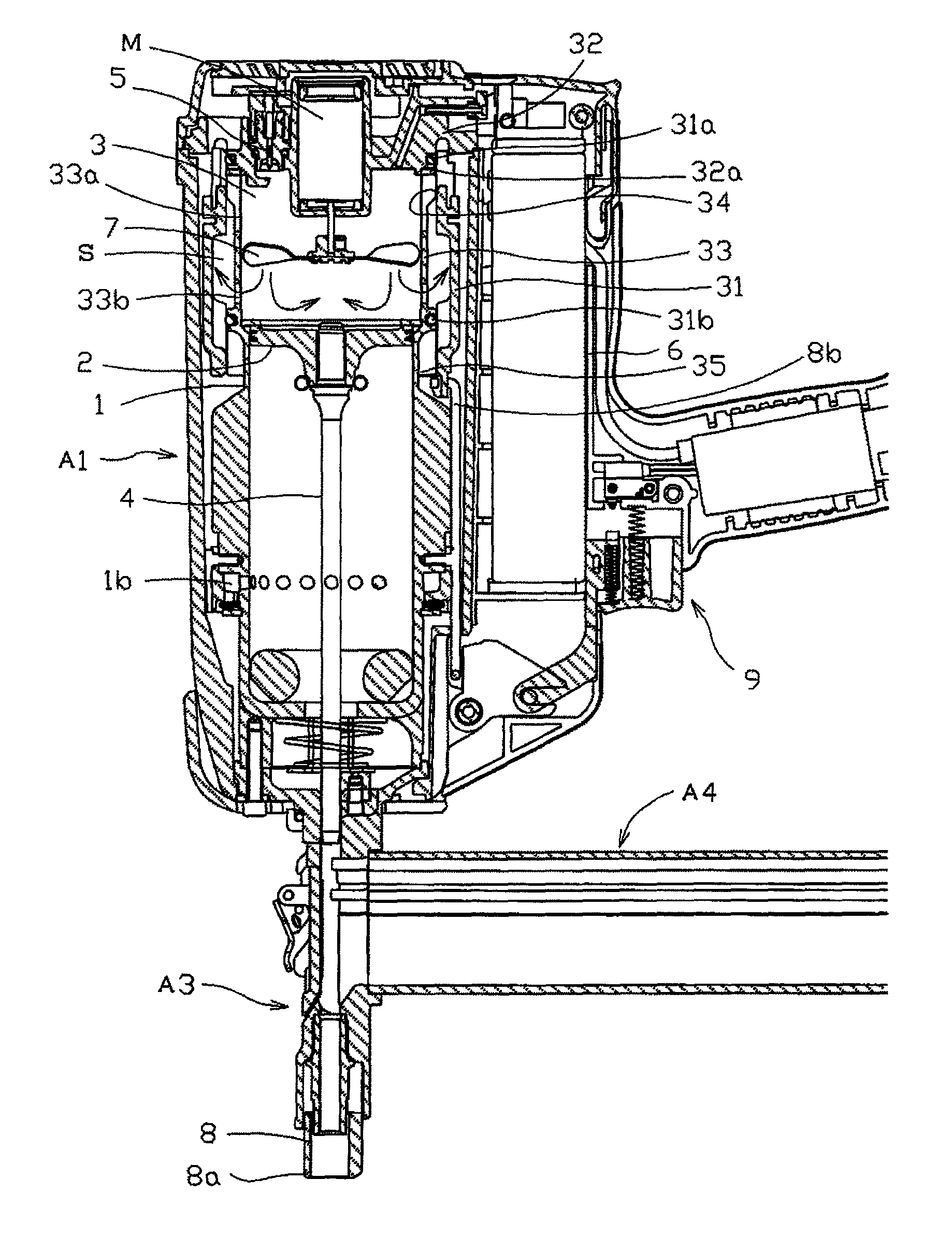
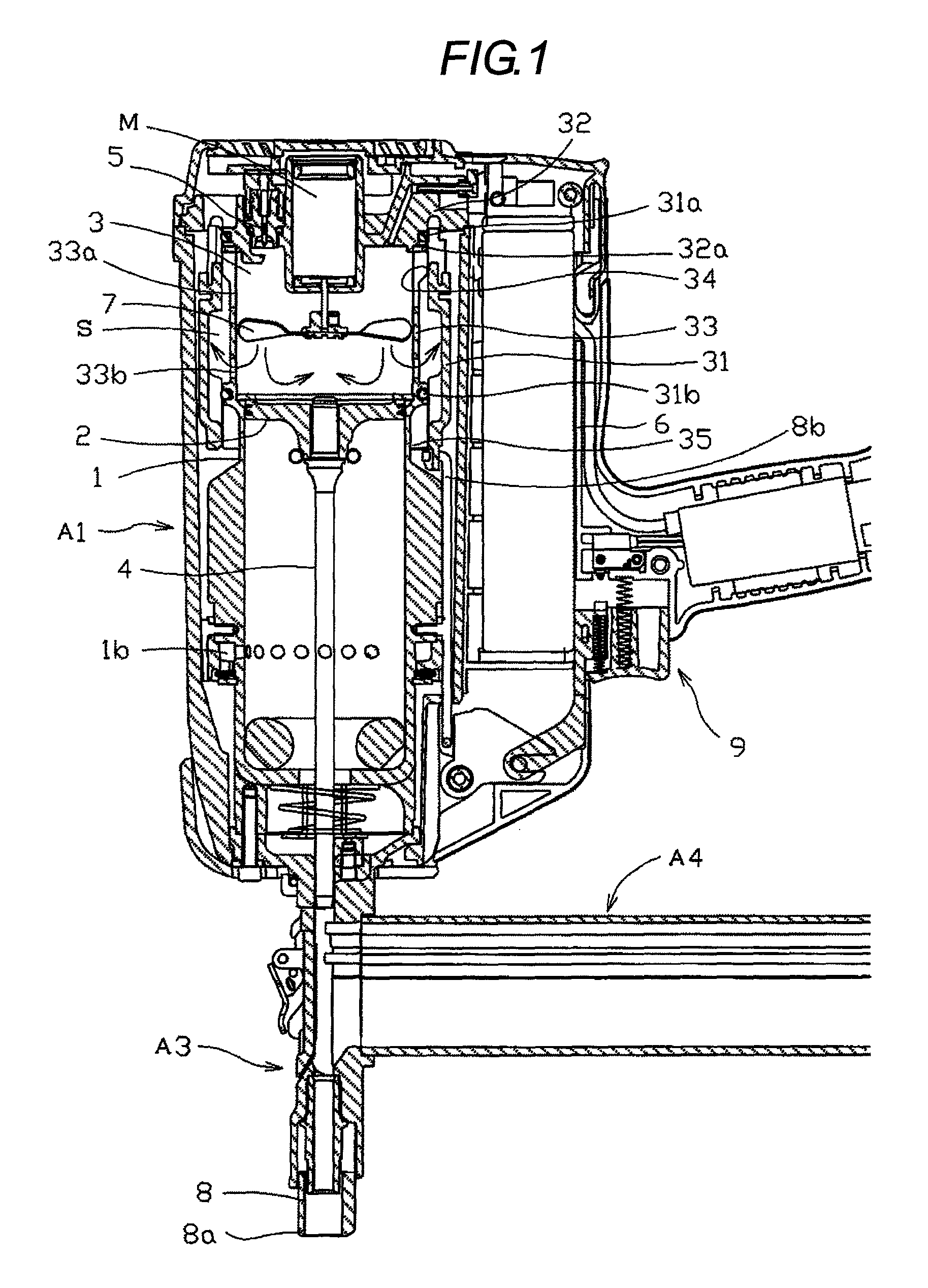
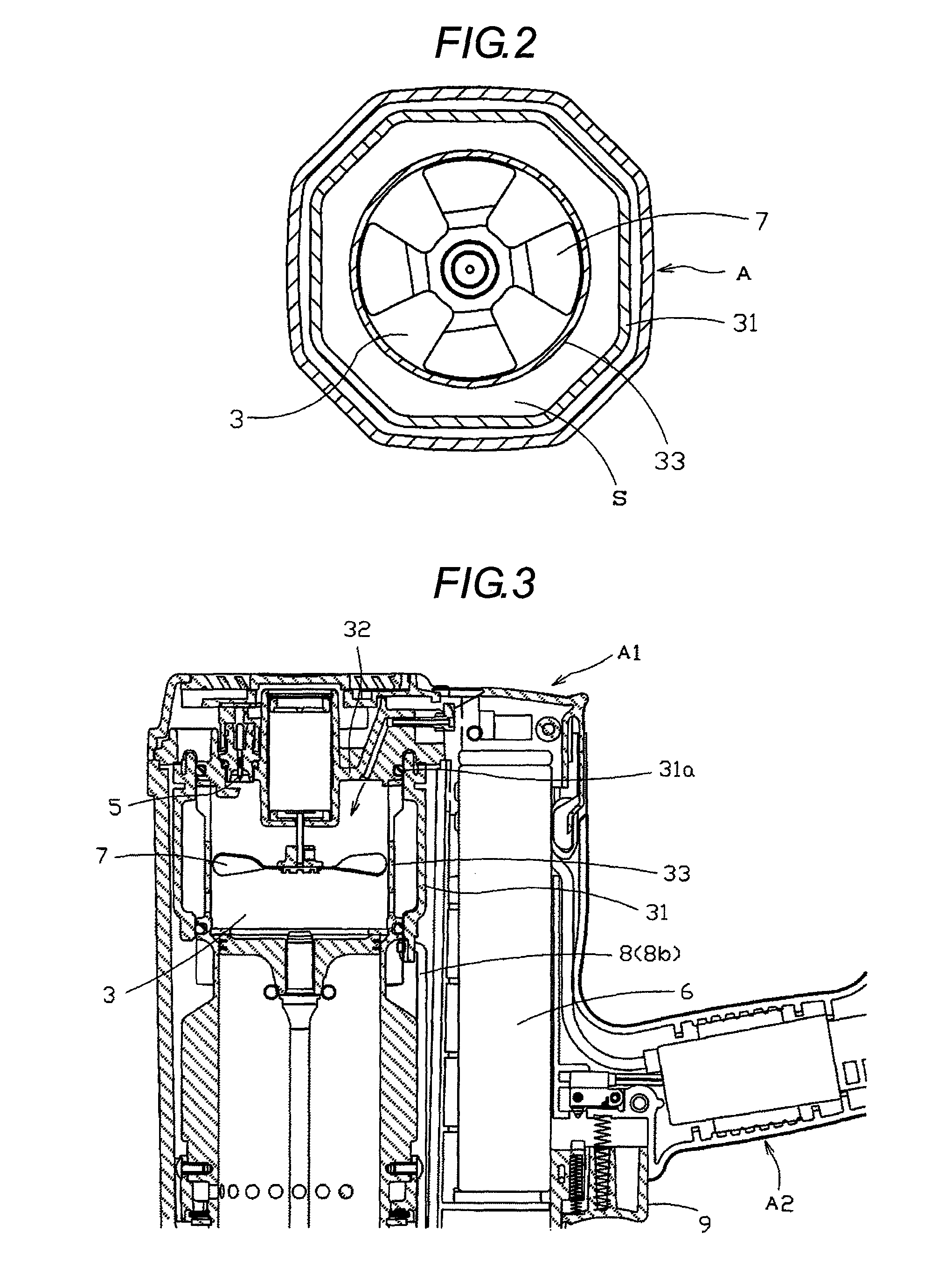
[0040]FIGS. 1 and 2 respectively show a gas internal combustion type nailing machine A. This nailing machine A includes: a nailing machine main body A1 for accommodating therein a drive mechanism portion, a gas fuel cartridge and the like; a grip A2 formed integrally with the nailing machine main body A1; a nose portion A3 having a mounting portion for mounting a magazine A4 projecting from the lower portion (in FIG. 1) of the nailing machine main body A1; and, other composing elements.

[0041]The drive mechanism portion to be accommodated into the nailing machine main body A1 includes: a cylindrical-shaped striking cylinder 1; a striking piston 2 which can be reciprocatingly moved in the vertical direction (in FIG. 1) within the striking cylinder 1; a combustion chamber 3 formed of a space which is surrounded by a tubular-shaped movable housing 31 and ...

second exemplary embodiment

[0056]FIG. 4 shows an improved structure (according to a second exemplary embodiment of the invention) of a combustion chamber for use in a gas internal combustion type nailing machine of a head valve type. This gas internal combustion type nailing machine A is basically similar in structure to the gas internal combustion type nailing machine according to the first exemplary embodiment of the invention and thus the duplicate description of the structure portions thereof in common with the first exemplary embodiment is in principle omitted here.

[0057]The present combustion chamber 3 includes on the upper end of the striking cylinder 1: a separation portion 11 for separating the interior portion of the striking cylinder 1 and the interior portion of the combustion chamber 3 from each other; and, a check valve 90 for opening and closing a penetration hole 11a formed in the separation portion 11.

[0058]The check valve 90, which is made of a plate spring, is structured such that it is nor...

third exemplary embodiment

[0072]Now, description will be given below of a third exemplary embodiment according to the invention with reference to FIGS. 5 to 8.

[0073]FIGS. 5 and 6 respectively show a gas internal combustion type nailing machine A. This nailing machine A includes: a nailing machine main body A1 for accommodating therein a drive mechanism portion, a gas fuel cartridge and the like; a grip A2 formed integrally with the nailing machine main body A1; a nose portion A3 having a mounting portion for mounting a magazine A4 projecting from the lower portion (in FIG. 5) of the nailing machine main body A1; and, other composing parts.

[0074]The drive mechanism portion to be accommodated into the nailing machine main body A1 includes: a cylindrical-shaped striking cylinder 1; a striking piston 2 which can be slid reciprocatingly in the vertical direction (in FIG. 5) within the striking cylinder 1; a combustion chamber 3 formed of a space which is surrounded by a tubular-shaped movable housing 31 and an up...


PUM


Abstract

In a gas internal combustion type nailing machine, a tubular-shaped sleeve is fixed between a movable housing and a fan. Between the movable housing and sleeve, an annular space portion is formed. In such portions of the sleeve as existing respectively upwardly and downwardly of the fan, there are formed communication holes and in communication with the annular space portion. Mixed gas blown out by the fan flows through the lower communication hole and returns from the annular space portion to the combustion chamber through the upper communication hole.

Description

TECHNICAL FIELD[0001]The present invention relates to a nailing machine of a gas internal combustion type which is used to drive a nail such as an ordinary nail and a drive screw and, specifically, the invention relates to an improved structure of a combustion chamber formed in such nailing machine.BACKGROUND ART[0002]Conventionally, there has been already known well a gas internal combustion type nailing machine (for example, see the patent reference 1) structured in the following manner: that is, a combustion chamber formed in the nailing machine includes a movable housing portion, and the movable housing portion can be opened and closed in linking with the operation of a contact member; in the closed state of the combustion chamber, combustible gas is supplied into the combustion chamber, the combustible gas and air are mixed together thereby rotating a fan, the thus mixed gas is ignited using a spark plug and is thereby combusted explosively, and the resultant high gas pressure ...

Claims


Application Information

Patent Timeline
Patent Type & Authority Patents(United States)
IPC IPC(8): B25C1/08
CPCB25C1/08F02B63/02F01B11/04F02B71/04B25C1/18F02B39/16
Inventor TANAKA, HIROSHITAKEMURA, HAJIME
Owner MAX CO LTD
Why Eureka
Try Eureka