Rail

a technology for railings and railings, applied in the field of rails, can solve the problems of saving time and labor in the construction of railings, and achieve the effect of reducing time and labor and reducing labor

Inactive Publication Date: 2012-02-14
HARDER WILLARD J
View PDF41 Cites 9 Cited by
  • Summary
  • Abstract
  • Description
  • Claims
  • Application Information

AI Technical Summary

Benefits of technology

[0012]The invention comprises a railing for a deck and stair having top and bottom rails connected to upright posts anchored to supports. Upright spindles extended between the top and bottom rails have opposite ends located in surface contact with the rails. Anchor balls or ball connectors support the spindles on the rails. Fasteners, such as deck screws, secure the anchor balls to the rails and maintain the knobs in firm engagement with the rails. The spindles are cylindrical metal tubes, such as coated aluminum tubes. The spindles can be square or multi-sided metal or plastic tubes. The opposite ends of the spindles are telescoped over the anchor balls to retain the spindles in fixed upright positions between the top and bottom rails. The anchor balls have hemispherical configurations with a size to accommodate the inside walls of the spindles with a tight annular friction or force fit. The opposite ends of the spindles have end surfaces located in surface engagement with the rails. The tight friction fit relation between the anchor balls and inside walls of the spindles provide annular seals to prevent moisture, water, dust, and dirt from entering the spaces with the spindles. The anchor balls have a plurality of outwardly directed continuous annular ribs which flex inwardly when the spindles are telescoped over the anchor balls. The ribs on each anchor ball are located in planes normal to the axis of the hole through the body of the anchor ball. The ribs are separate sealing rings located in a force fit biased relation with the inside walls of the spindles. The anchor balls allow the spindles to be moved to inclined positions relative to the rails without modifications or additional structures or welds. The anchor balls are pre-installed on the rails prior to assembly on the posts. This allows the railing to be constructed with a minimum of time and labor.
[0013]An alternate embodiment of the spindle comprises an elongated metal or plastic tube having an inside square wall with inwardly directed longitudinal projections or ribs. The projections are forced into the sides of the anchor balls when the spindles are pressed onto the anchor balls. The projections prevent the spindles from rotating relative to the anchor balls. The anchor balls are installed on the rails with a minimum of time and labor and with conventional tools. The ends of the spindles cover the anchor balls rendering the railing aesthetically pleasing and decorative.

Problems solved by technology

This saves time and labor in the construction of a railing.

Method used


Image

  • Rail
  • Rail
  • Rail

Examples


Embodiment Construction

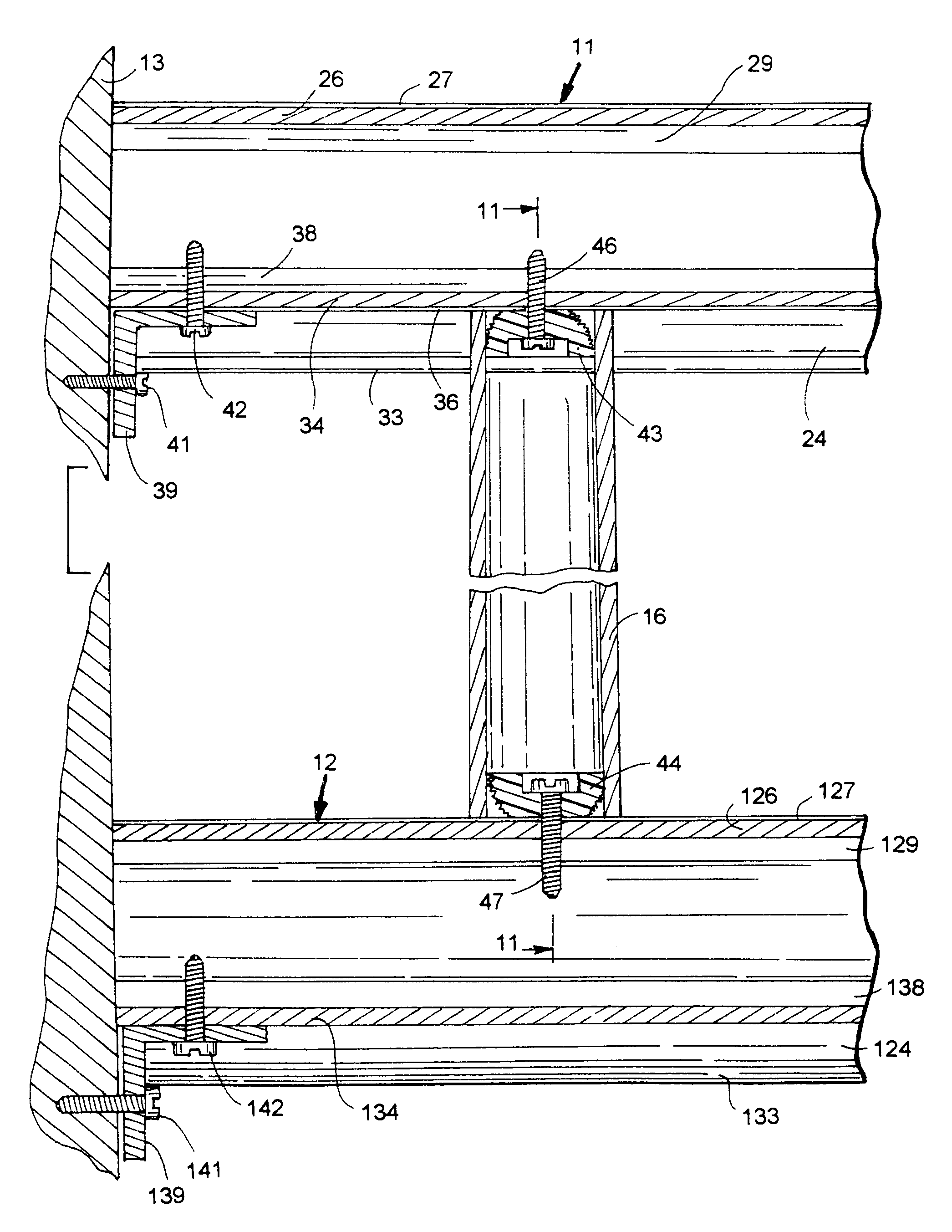
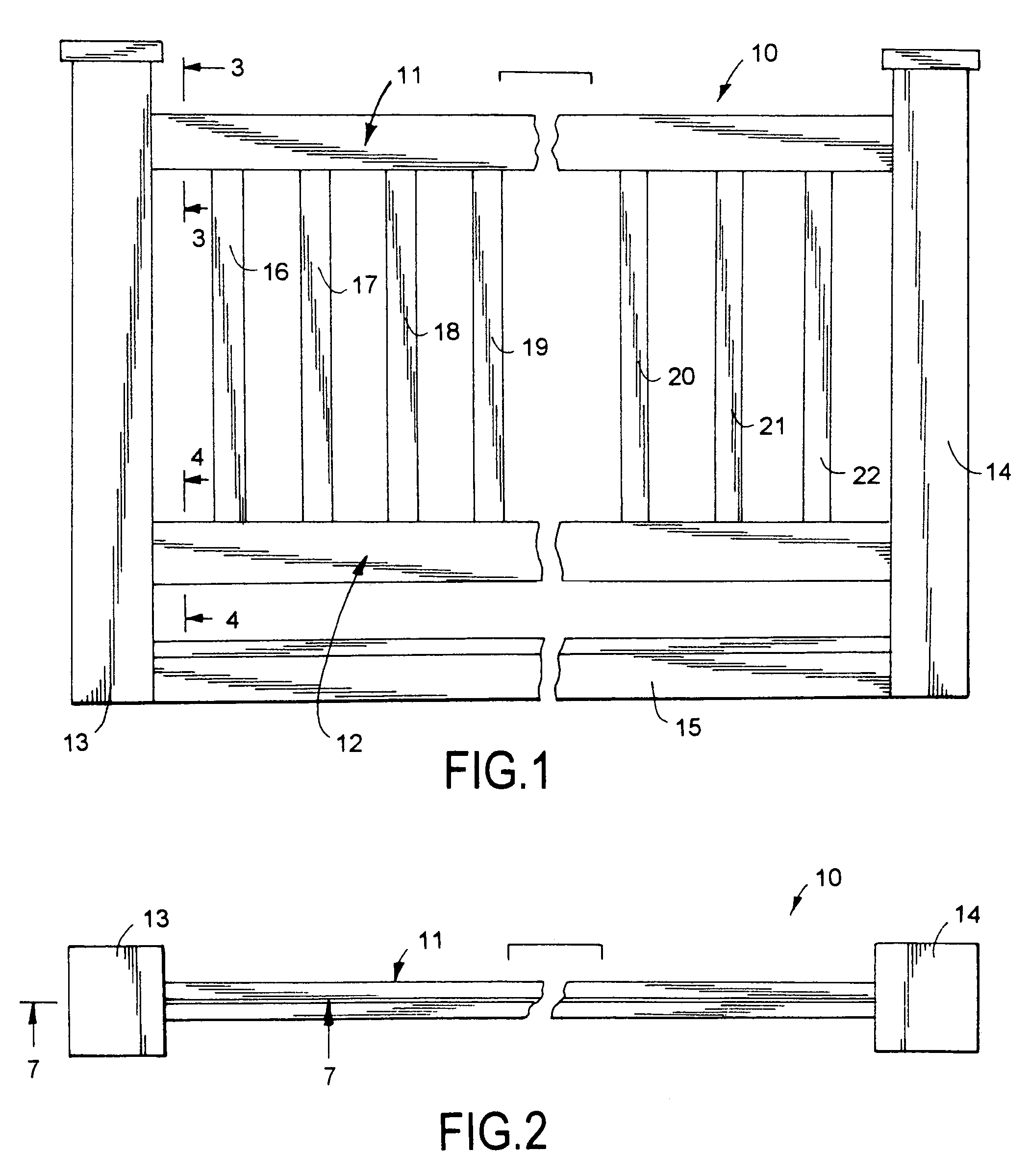
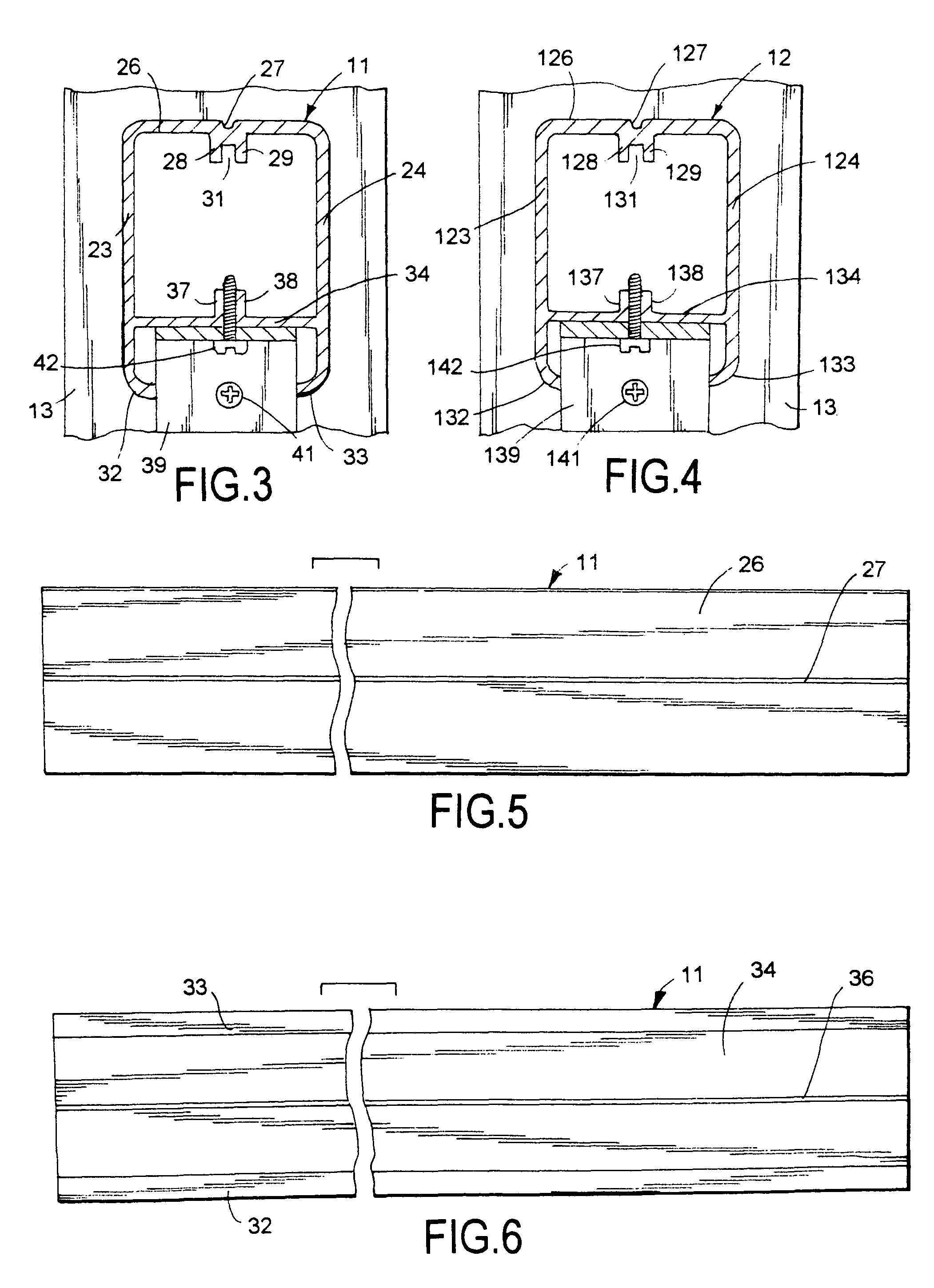
[0029]Railing system 10, shown in FIGS. 1 and 2, has horizontal top and bottom rails 11 and 12 secured to upright columns or posts 13 and 14. Posts 13 and 14 are square wood members secured to separate sections of a deck or platform 15. Other shapes and materials, including metal, ceramic, concrete, composite materials and plastic, can be used for posts 13 and 14. The bottom ends of posts 13 and 14 can be anchored in the ground. A plurality of upright spindles 16 to 22 extend between rails 11 and 12. Spindles 16 to 22 are cylindrical tubes, such as aluminum tubes. Adjacent spindles are laterally spaced from each other a distance according to building codes. Opposite ends of each spindle are anchored to rails 11 and 12 to maintain uniform spacing between adjacent spindles. Railing system 10, shown in FIG. 1, is a section of a railing structure having top and bottom rails secured to posts 13 and 14 and additional posts. The upright spindles extend between and are anchored to the top a...


PUM


Abstract

A railing system for decks and stairs has identical top and bottom metal extruded rails with upright spindles extended between the rails. Anchor balls secured to the rails with fasteners hold the spindles in assembled relation with the rails. The anchor balls have continuous circumferential ribs located in a force fit relationship with inside surfaces of the spindles.

Description

RELATED APPLICATIONS[0001]This application is a continuation-in-part of Ser. No. 12 / 150,284 filed Apr. 28, 2008, now U.S. Pat. No. 7,748,686. Application Ser. No. 12 / 150,284 is a division of U.S. application Ser. No. 11 / 056,566 filed Feb. 14, 2005, now U.S. Pat. No. 7,438,282. Application Ser. No. 11 / 056,566 is a division of application Ser. No. 10 / 636,034 filed Aug. 8, 2003, now U.S. Pat. No. 6,932,329. Application Ser. No. 10 / 636,034 claims the priority date of U.S. Provisional Patent Application Ser. No. 60 / 418,280 filed Oct. 15, 2002.FIELD OF THE INVENTION[0002]The invention is the art of rails for deck railings, fences and barriers used to separate environmental areas. The particular field of the invention relates to residential and commercial rails and railings having upright laterally spaced balusters or spindles attached to rails.BACKGROUND OF THE INVENTION[0003]Residential decks and stairs have railings to separate these structures from adjacent areas and prevent persons fr...

Claims


Application Information

Patent Timeline
Patent Type & Authority Patents(United States)
IPC IPC(8): E04H17/14
CPCE04F11/1834E04F11/1836E04F2011/1887E04F2011/1897E04F2011/1823E04F2011/1821E04F2011/1827E04F11/1817E04F2011/1819
Inventor HARDER, WILLARD J.
Owner HARDER WILLARD J
Why Eureka
Try Eureka