
Apparatus and method for controlling a damper in a gas-fired appliance

a technology for gas-fired appliances and dampers, which is applied in lighting and heating apparatus, ventilation systems, heating types, etc., can solve the problems of increasing installation costs, many gas-fired appliances, particularly residential water heaters, do not include power sources with sufficient voltage to reliably, 10 to 30 millivolts

Active Publication Date: 2012-02-14
FIELD CONTROLS
View PDF16 Cites 31 Cited by
  • Summary
  • Abstract
  • Description
  • Claims
  • Application Information

AI Technical Summary

Problems solved by technology

However, such designs typically require the routing of a power source to the location of the gas-fired appliance, potentially increasing installation costs.
However, many gas-fired appliances, particularly residential water heaters, do not include power sources having sufficient voltage to reliably operate a damper motor.
While some such water heaters may utilize a thermocouple to operate a magnetic pilot safety switch, such thermocouples typically generate only 10 to 30 millivolts, and do not supply sufficient power to drive a damper motor.
Because of such control limitations, flue dampers are often not provided on residential water heaters, thereby sacrificing potential improvements in energy efficiency.

Method used


Image

  • Apparatus and method for controlling a damper in a gas-fired appliance
  • Apparatus and method for controlling a damper in a gas-fired appliance
  • Apparatus and method for controlling a damper in a gas-fired appliance

Examples


Embodiment Construction

[0023]While this invention is susceptible of embodiment in many different forms, there are shown in the drawings and will herein be described in detail, certain specific embodiments with the understanding that the present disclosure should be considered as an exemplification of the principles of the invention and is not intended to limit the invention to the embodiments so illustrated or described.

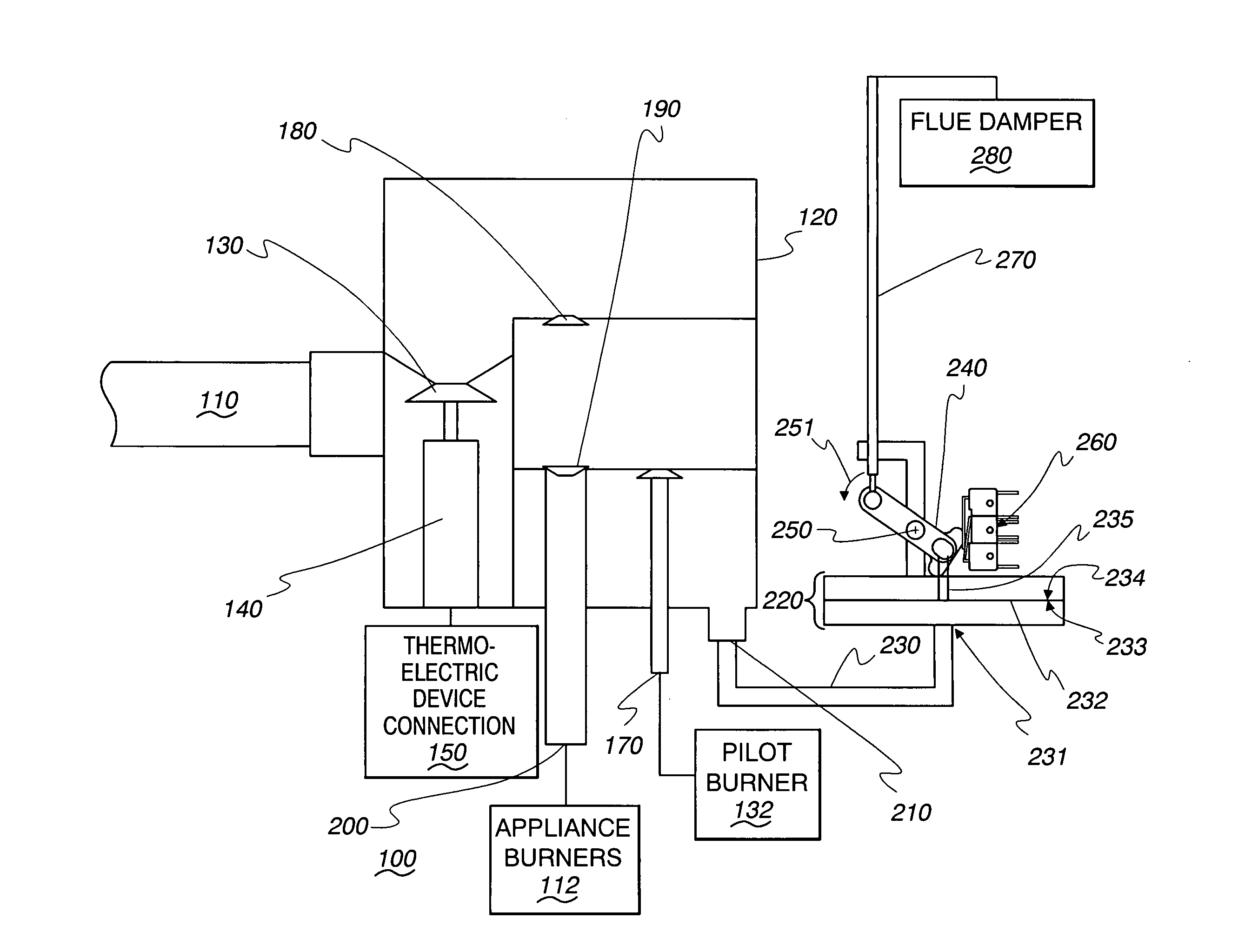
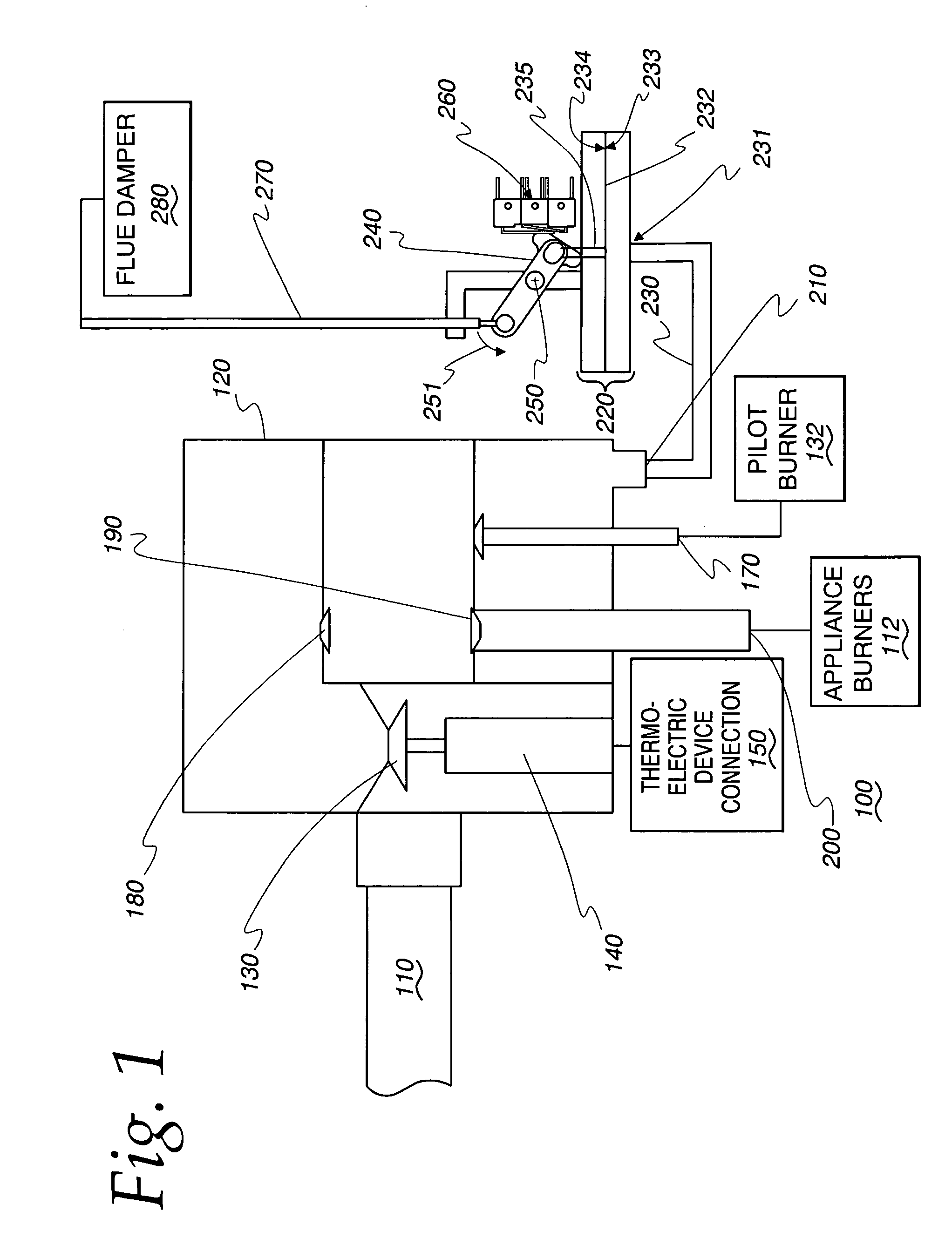
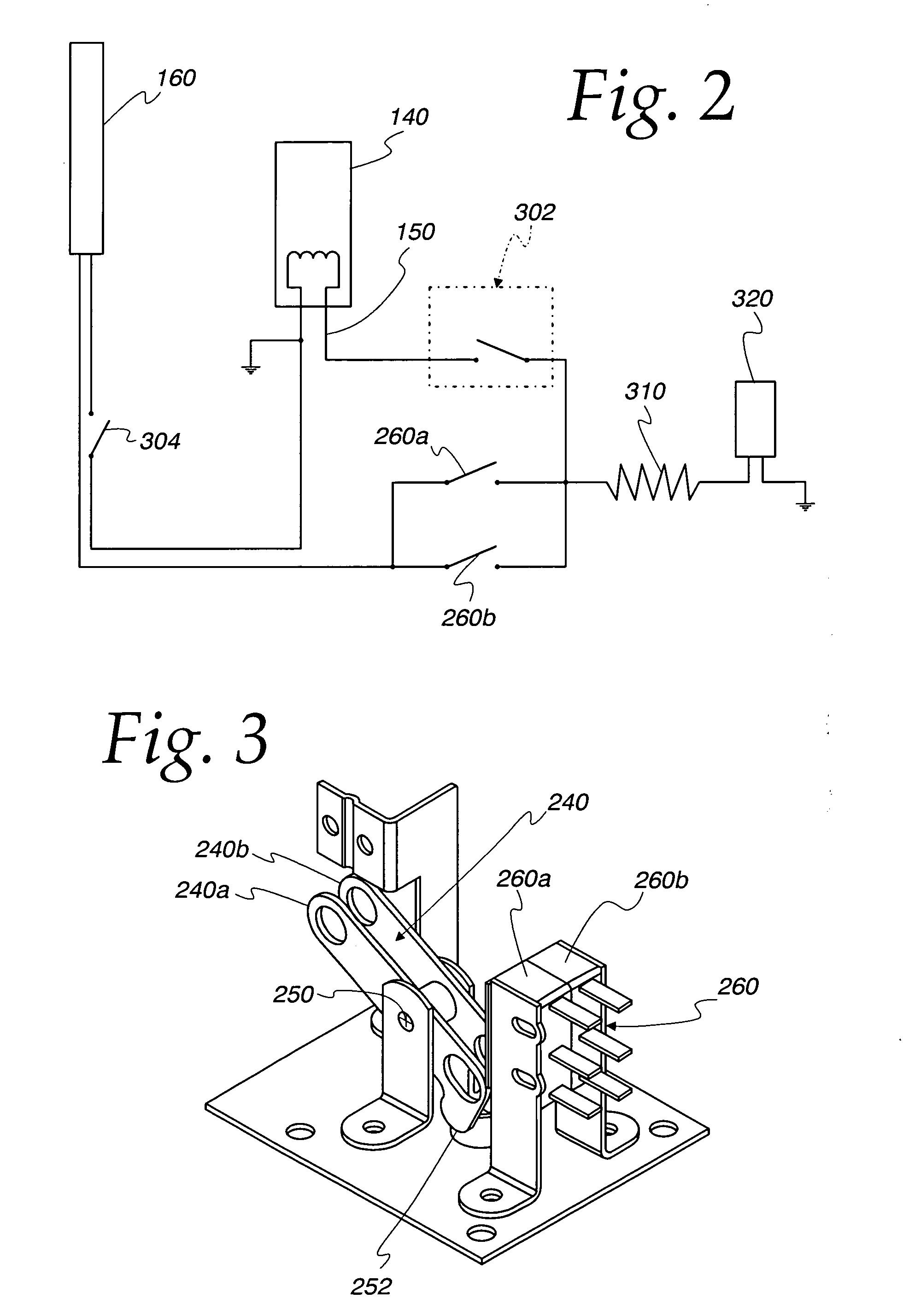
[0024]Referring initially to FIG. 1, a portion of a gas-fired appliance, such as a water heater, is illustrated. Gas fired appliance 100 receives combustible gas, such as natural gas, via supply line 110. The gas is supplied at a pressure greater than the ambient air pressure in which the main appliance burners 112 (shown schematically) operate. Gas is fed into control body 120 and through pilot valve 130, which supplies gas to a pilot burner 132 (shown schematically). Once pilot burner 132 is ignited, pilot valve 130 is maintained in an open position by pilot valve magnet 140, which is en...


PUM


Abstract

A damper mechanism for a gas-fired appliance is disclosed. The damper mechanism is mechanically operated in response to changes in pressure within a portion of the appliance. Changes in gas pressure operate to displace a diaphragm, thereby moving a linkage attached to a flue damper, such that the damper can be moved between open and closed positions. An interim damper control activation arm can pivot in response to movement of the linkage to actuate electrical switches, which act to close a magnetic pilot valve when the damper is in a partially-opened or partially-closed position.

Description

TECHNICAL FIELD[0001]The present invention relates generally to gas-fired appliances, and, more particularly, to a damper control mechanism for a water heater or other gas-fired appliance.BACKGROUND OF THE INVENTION[0002]Many gas-fired appliances, such as boilers or water heaters, include burners that fire to raise the temperature of materials, such as water, contained within a tank. In many such appliances, the burners periodically cycle on and off. When the contents of the tank fall below a desired minimum temperature, a call for heat is triggered, which initiates the firing of a main gas burner assembly. The resulting heat generated by the burner acts to raise the tank temperature. When the tank temperature reaches a desired maximum threshold, the main burner is deactivated, until such time as the tank cools and again falls below the minimum desired temperature. A small pilot burner can be provided to maintain a small flame under normal operation, which flame is used to ignite th...

Claims


Application Information

Patent Timeline
Patent Type & Authority Patents(United States)
IPC IPC(8): F23N3/00F23N1/02F23L11/00H01H3/16H01H25/00F24F7/00
CPCF23L11/005F23L13/02F23N5/102F23N5/203F23N5/242F23N2035/04F23N2041/04F23N2235/04F23N2241/04
Inventor GUZOREK, STEVEN E.
Owner FIELD CONTROLS
Learn More