Thickness distribution control for electroplating

a thickness distribution control and electroplating technology, applied in the direction of electrolysis process, electrolysis components, cells, etc., can solve the problems of ineffective control and adjustment of the inability to monitor in-situ the distribution of the electroplating material, and the inability to control the thickness distribution of the obj

Active Publication Date: 2012-02-14
E INK CORPORATION
View PDF15 Cites 15 Cited by
  • Summary
  • Abstract
  • Description
  • Claims
  • Application Information

AI Technical Summary

Problems solved by technology

However, the method has the disadvantage that cylinders of different diameters or lengths would need dedicated cup-like shields of different dimensions.
Besides, the method can not monitor in-situ the distribution of the electroplated material.
The method disclosed, however, is not effective for controlling and adjusting the thickness distribution on the object because both the distribution of electrical field and deposition time along the cylinder's longitudinal axis are not controlled.
While the reference addresses several problems and quality issues in the electroplating of the rotogravure cylinder, the thickness distribution of the plated material cannot be controlled for the same reason as described for the method of U.S. Pat. No. 5,318,683.

Method used


Image

  • Thickness distribution control for electroplating
  • Thickness distribution control for electroplating
  • Thickness distribution control for electroplating

Examples


Embodiment Construction

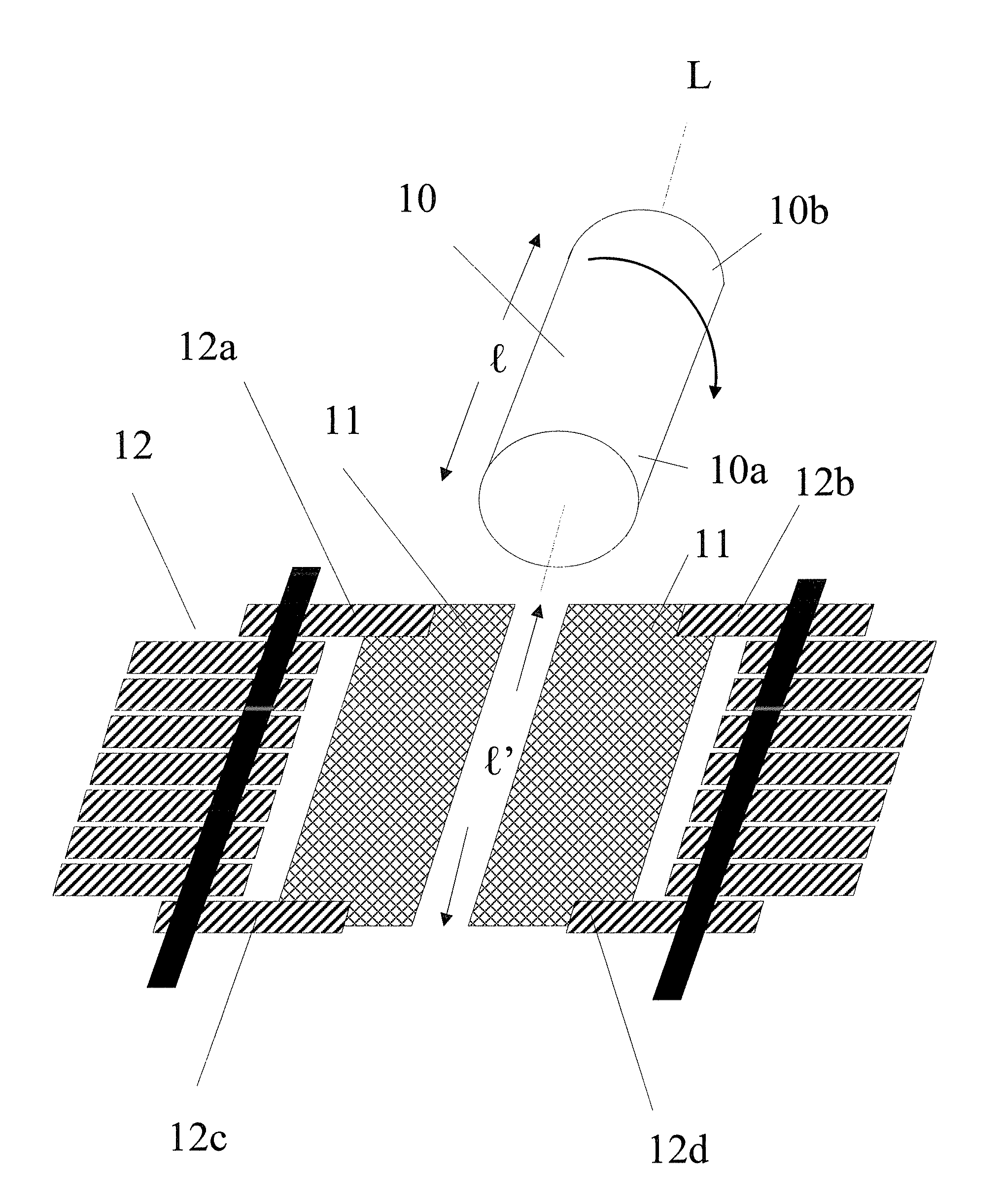
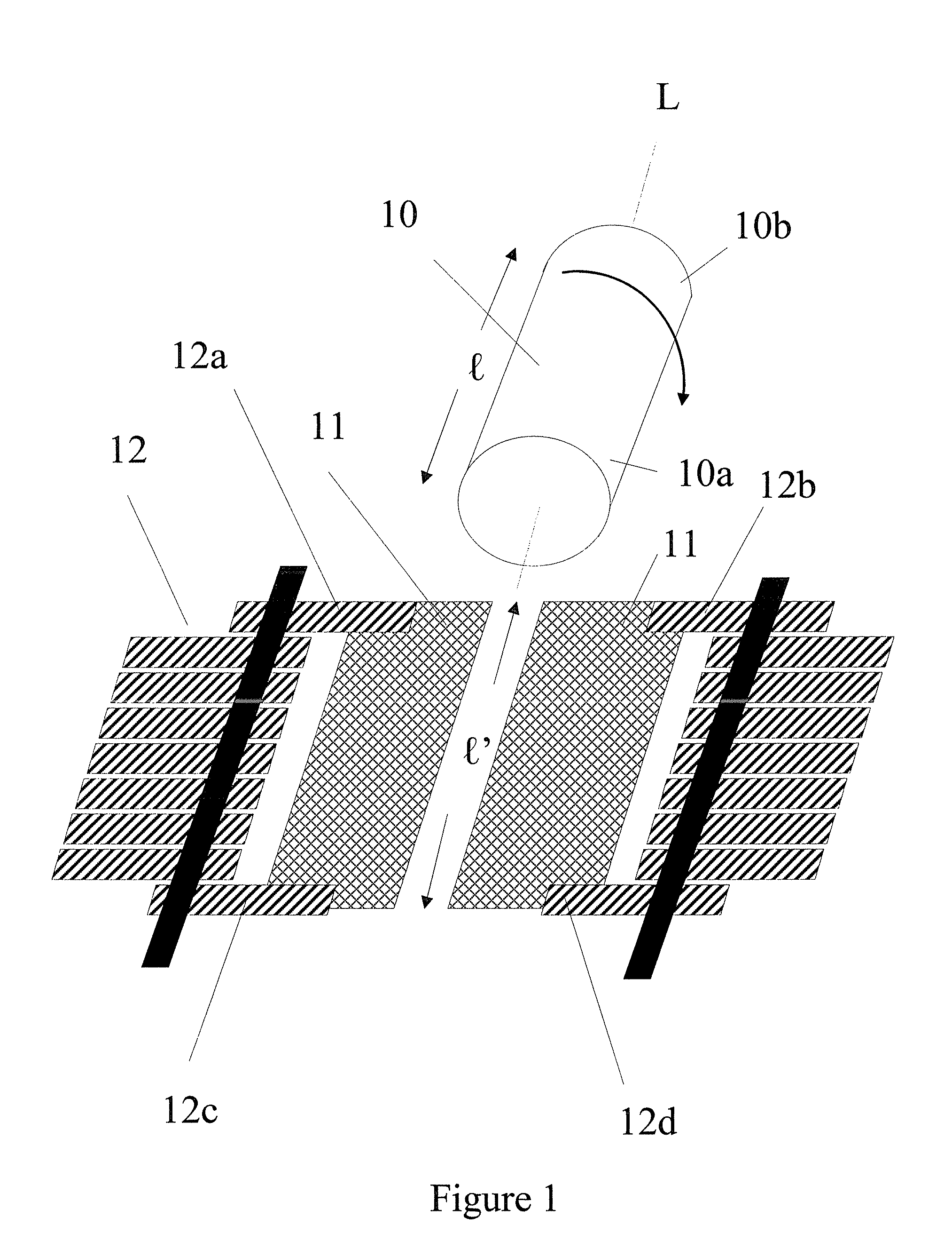
[0021]This invention provides assemblies and methods to monitor in situ, control and adjust the thickness distribution of an electroplated material on an object in an electroplating process. The object can be of any shape as long as it can be electrically charged. A cylinder-shaped object that rotates axially is particularly suitable for the present invention.

[0022]During the process, the object to be electroplated is at lease partially immersed in an electroplating bath and rotates axially during electroplating. The layout of the object and anode(s) can be horizontal, vertical or tilted, although the horizontal layout may be preferred. For the horizontal layout, the object can be partially or completely immersed in an electroplating bath. In contrast, the object must be completely immersed in an electroplating bath for the vertical and tilted layouts.

[0023]The anode may be a non-dissolvable anode, dissolvable anode bar or plate. It may include a dissolvable metal or alloy pellets o...


PUM

PropertyMeasurementUnit
thicknessaaaaaaaaaa
resistanceaaaaaaaaaa
thickness distributionaaaaaaaaaa

Abstract

The invention is directed to an assembly for electroplating comprising an electroplating bath and non-conductive plates. The invention is also directed to an assembly for electroplating comprising an electroplating bath, elements with electrically adjustable resistance, and ampere-hour meters. The invention is further directed to methods for monitoring, controlling and adjusting the thickness distribution of an electroplated material on an object. The object can be of any shape as long as it can electrically charged.

Description

[0001]This application claims priority to U.S. provisional application No. 60 / 758,340, filed Jan. 11, 2006. The content of which is incorporated herein by reference in its entirety.BACKGROUND OF THE INVENTION[0002]1. Field of the Invention[0003]This invention is directed to assemblies and methods for monitoring in situ, controlling and adjusting the thickness distribution of an electroplated material on an object in an electroplating process. The object can be of any shape as long as it can be electrically charged.[0004]2. Description of Related Art[0005]U.S. Pat. No. 4,659,446 discloses cup-like shields of a non-conductive acid-resistant material that are secured at opposite ends of a cylinder for rotation with the cylinder and extend radially outwardly. The shields have a configuration such as to control the thickness of the metal deposited on the cylinder. However, the method has the disadvantage that cylinders of different diameters or lengths would need dedicated cup-like shiel...

Claims


Application Information

Patent Timeline
Patent Type & Authority Patents(United States)
IPC IPC(8): C25D21/12
CPCC25D5/04C25D21/12C25D17/10C25D17/007C25D17/008
Inventor KANG, GARY YIH-MINGCHAUG, YI-SHUNG
Owner E INK CORPORATION
Why Eureka
Try Eureka