Suspension system for vehicle

a suspension system and vehicle technology, applied in the direction of cycle equipment, transportation and packaging, instruments, etc., can solve the problems of system failure to provide satisfactory ride comfort and vibration cannot be effectively damped, and achieve the effect of low reduction gear ratio and low positive/negative efficiency produ

Active Publication Date: 2012-02-14
TOYOTA JIDOSHA KK
View PDF18 Cites 20 Cited by
  • Summary
  • Abstract
  • Description
  • Claims
  • Application Information

AI Technical Summary

Benefits of technology

[0006]In the suspension system according to the invention, when the vehicle-body vibrations are constituted principally by relatively low-frequency vibrations such as vibrations of sprung-portion resonance-frequency range, the vehicle-body vibrations are effectively damped by the displacement force that is generated by each of the displacement force generators. When the vehicle-body vibrations are constituted principally by relatively high-frequency vibrations, it is possible to restrain deterioration of ride comfort of the vehicle, by limiting generation of the displacement force that could affect performance of damping such vibrations of relatively high frequency range. The suspension system of the present invention provides such a technical advantage, and accordingly has a high practicability.
[0096]In the system according to this mode (24), the reduction gear ratio, i.e., a ratio of an actuation amount of the actuator to a motion amount of the electromagnetic motor is relatively low. It can be considered that the above-described positive / negative efficiency product is, in general, reduced by employing the speed reducer having a low reduction gear ratio. In view of this, the system of this mode (24) can be considered as a kind of the system in which the actuator having a relatively low positive / negative efficiency product is employed. The employment of the speed reducer having the low reduction gear ratio permits the electromagnetic motor to be made compact in size. The “speed reducer” recited in this mode (24) may have a construction that is not particularly limited. For example, it is possible to employ, as the speed reducer, any one of various kinds of speed reducers such as a harmonic gear set (that is also called “harmonic drive” or “strain wave gearing”) and a hypocycloid gear set.

Problems solved by technology

However, there is a problem that the suspension system fails to provide satisfactory ride comfort, because the vibration cannot be effectively damped due to difficulty for actuation of each displacement force generator to sufficiently follow the vibration, particularly, when frequency of the vibration is high, and because the displacement force is generated with a delay relative to the vibration having relatively high frequency.

Method used


Image

  • Suspension system for vehicle
  • Suspension system for vehicle
  • Suspension system for vehicle

Examples


Embodiment Construction

[0118]There will be described an embodiment of the present invention, by reference to the accompanying drawings. It is to be understood that the present invention is not limited to the following embodiment, and may be otherwise embodied with various changes and modifications, such as those described in the foregoing “MODES OF THE INVENTION”, which may occur to those skilled in the art.

(i) Overall Construction of Suspension System

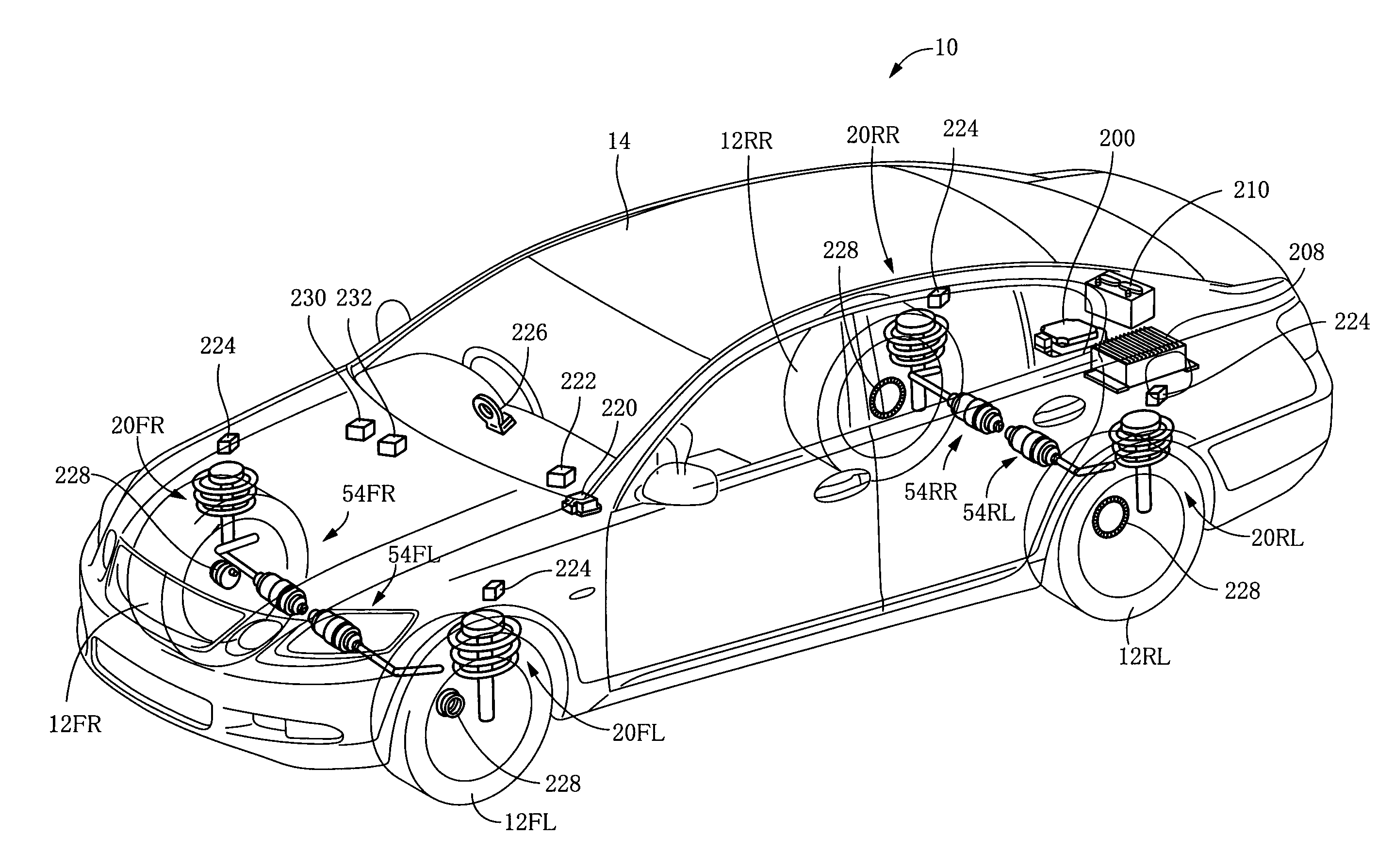
[0119]FIG. 4 schematically shows a suspension system 10 for a vehicle, which is constructed according to an embodiment of the invention. The suspension system 10 includes four suspension devices 20FR, 20FL, 20RR, 20RL which are provided for a front right wheel 12FR, a front left wheel 12FL, a rear right wheel 12RR and a rear left wheel 12RL of the vehicle, respectively. Each of the four suspension devices 20 is disposed between a body 14 of the vehicle and a corresponding one of the four wheels 12. The suspension devices 20FR, 20FL provided for the front whe...


PUM


Abstract

A suspension system for a vehicle, including (a) four displacement force generators (152) each configured to generate a displacement force forcing sprung and unsprung portions of the vehicle toward or away from each other; and (b) a control unit (200) configured to control the displacement force that is to be generated by each displacement force generator. The control unit is capable of executing a plurality of vibration damping controls concurrently with each other, by controlling the displacement force, so as to damp a composite vibration containing a plurality of different vehicle-body vibrations which are to be damped by the respective vibration damping controls. The control unit is configured to refrain from executing at least one of the vibration damping controls for damping one of the vehicle-body vibrations that is not required to be damped, in a low vibration intensity situation in which intensities of sprung-portion resonance-frequency vibration components in respective four sprung portions of the vehicle are lower than a threshold intensity degree.

Description

[0001]This application is based on Japanese Patent Application No. 2008-138230 filed on May 27, 2008, the content of which is incorporated hereinto by reference.TECHNICAL FIELD[0002]The present invention relates to a suspension system for a vehicle, which is provided with a device including an electromagnetic motor and configured to generate, based on a force generated by the electromagnetic motor, a displacement force causing sprung and unsprung portions of the vehicle to be displaced toward or away from each other.BACKGROUND ART[0003]In recent years, there is a study of, as a suspension system that is to be provided in a vehicle, a suspension system including displacement force generators provided for respective wheels of the vehicle, wherein each of the displacement force generators includes an electromagnetic motor, and is configured to generate, based on a motor force generated by the electromagnetic motor, a displacement force causing sprung and unsprung portions of the vehicl...

Claims


Application Information

Patent Timeline
Patent Type & Authority Patents(United States)
IPC IPC(8): B60G17/016
CPCB60G17/0157B60G17/016B60G17/025B60G2202/42B60G2400/102B60G2400/20
Inventor KAJINO, HIDENORICHO, JAE-SUNG
Owner TOYOTA JIDOSHA KK
Why Eureka
Try Eureka