
Prefabricated structural element

a prefabricated and structural element technology, applied in the direction of girders, joists, transoms, etc., can solve the problems of inconvenient placement of fasteners in boards, inconvenient construction of headers, gaps in interior walls, etc., to facilitate interior finishing, facilitate construction, and facilitate construction. effect of building

Active Publication Date: 2012-02-21
KISCH DENNIS R +1
View PDF23 Cites 7 Cited by
  • Summary
  • Abstract
  • Description
  • Claims
  • Application Information

AI Technical Summary

Benefits of technology

[0008]In view of the foregoing disadvantages inherent in the known types of structure-forming elements now present in the prior art, the present invention provides a new prefabricated structural element wherein the same facilitates the construction of a building by providing a preformed element that is easily cut to fit differently-sized openings in a building and that facilitate the finishing of the interior of the building after the element is installed.

Problems solved by technology

The on-site construction of the header can be relatively time consuming as compared to other framing done on-site, and fastener placement in the boards may not be optimal for the greatest strength.
The fabrication of headers in this manner does not always result in a structural element that is the same thickness as the rest of the wall, which can cause gaps in the interior of the wall.
Various prefabricated structural members have been proposed for use as headers (or as other structural elements) in buildings, which can eliminate the need to perform on-site fabrication and provide a more uniform quality for the header, but the known designs tend to employ a modified I-beam or box-beam configuration that can form gaps in the resulting walls which in turn may complicate insulation installation in the wall, as well as the finishing of the wall (such as with wall board) and the installation of decorative elements (such as curtain rods that tend to be installed above openings in a structure).
The additional parts complicates the assembly and inevitably makes it more expensive to assemble, and the limited area for secure attachment is positioned more toward one side of the beam assembly and thus requires that the builder make sure at each use that the correct side is positioned downwardly.

Method used


Image

  • Prefabricated structural element
  • Prefabricated structural element

Examples


Embodiment Construction

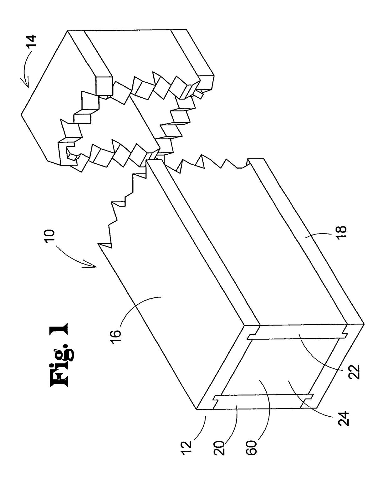
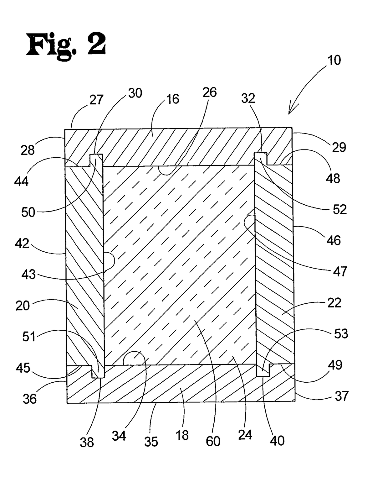
[0019]With reference now to the drawings, and in particular to FIGS. 1 and 2 thereof, a new prefabricated structural element embodying the principles and concepts of the present invention and generally designated by the reference numeral 10 will be described.

[0020]The structural element 10 of the invention is highly suitable for use in the construction of a building or other structure, and is especially useful for, although is not limited to, forming the framing elements above openings in the building structure sometimes referred to as a “header”. The structural element 10 has opposite longitudinal ends 12, 14 that may be rested on and attached to supporting elements, such as vertical structures in a wall.

[0021]The structural element 10 of the invention may comprise a first longitudinal member 16 and a second longitudinal member 18, and a first lateral member 20 and a second lateral member 22. The members 16, 18, 20, 22 each extend between the opposite longitudinal ends 12, 14 of th...


PUM


Abstract

A structural element for use in forming a structure, that includes first and second longitudinal members that extend between opposite ends of the element. The longitudinal members have inward and outward faces, and a pair of side faces extending between the inward and outward faces. The element includes first and second lateral members that extend between the first and second longitudinal members. The first and second lateral members each have an outer surface. The outer surface of the first lateral member is substantially flush with a side face of each longitudinal member to form a substantially planar surface extending across substantially an entirety of a first side surface of the element. The outer surface of the second lateral member is substantially flush with a side face of each longitudinal member to form a substantially planar surface extending across substantially an entirety of a first side surface of the element.

Description

BACKGROUND OF THE INVENTION[0001]1. Field of the Invention[0002]The present invention relates to structure-forming elements and more particularly pertains to a new prefabricated structural element that facilitates the construction of a building by providing a preformed element that is easily cut to fit differently-sized openings in a building and that facilitate the finishing of the interior of the building after the element is installed.[0003]2. Description of the Prior Art[0004]In the construction of a building or other structure, it is often desirable to create openings for doors and windows to permit egress and allow for light passage and ventilation. These openings require reinforced structural elements to be positioned above the opening to support the portion of the wall above the opening, and an element typically referred to as a “header” is employed that has greater strength than the usual stud-and-bay arrangement employed in the rest of the wall. Headers are most commonly f...

Claims


Application Information

Patent Timeline
Patent Type & Authority Patents(United States)
IPC IPC(8): E04C3/00
CPCE04C3/02E04C3/127E04C3/29E04C2003/023Y10S52/08
Inventor KISCH, DENNIS R.FROHREICH, TIMOTHY D.
Owner KISCH DENNIS R
Learn More