
Pre-filled hypodermic syringe fitted with a stoppering device

a technology of stoppering device and syringe, which is applied in the field of pre-filled hypodermic syringe fitted with stoppering device, can solve the problems of increasing the cost of producing such a syringe, the outer face of the tip cannot be sterilized, and the zone situated between these two elements is not accessible to the vapor, so as to avoid any bacterial contamination

Active Publication Date: 2012-02-21
LAB AGUETTANT SA
View PDF9 Cites 41 Cited by
  • Summary
  • Abstract
  • Description
  • Claims
  • Application Information

AI Technical Summary

Benefits of technology

The design enables efficient, clean separation of the obturator and tip, ensuring sterility and preventing contamination, while allowing for faster and cost-effective sterilization without material degradation, maintaining the integrity of the solution.

Problems solved by technology

However, since the removable stopper is mounted in a leaktight manner on the tip, the zone situated between these two elements is not accessible to the vapor.
The outer face of the tip cannot therefore be sterilized using the wet heat sterilization method.
The longer sterilization time increases the cost of producing such a syringe.
It also causes greater degradation of the plastic material of the body of the pre-filled syringe, thereby increasing the risk of products of degradation being released into the solution.
In addition, the prolonged exposure to high temperatures causes unacceptable degradation of certain active principles.
A further problem arises from the syringe being closed by a stopper.
This relaxation is caused by softening of the polypropylene at high temperature, and this compromises the leaktightness between the stopper and the tip.
However, the sterilization creates an adherence of the stopper to the tip, making it difficult for the user to remove the stopper.
The poor distribution of the stresses in the frangible zone makes it uncertain that the frangible zone will be broken completely by a single tilting movement, which generally forces the user to perform an alternative movement.
The presence of a thickness of material at the level of the frangible zone makes it all the more difficult to cleanly separate the obturator and the tip.
If a clean break is not obtained, particles may be produced when the tip is torn off, such that the solution contained in the syringe is contaminated.

Method used


Image

  • Pre-filled hypodermic syringe fitted with a stoppering device
  • Pre-filled hypodermic syringe fitted with a stoppering device
  • Pre-filled hypodermic syringe fitted with a stoppering device

Examples


Embodiment Construction

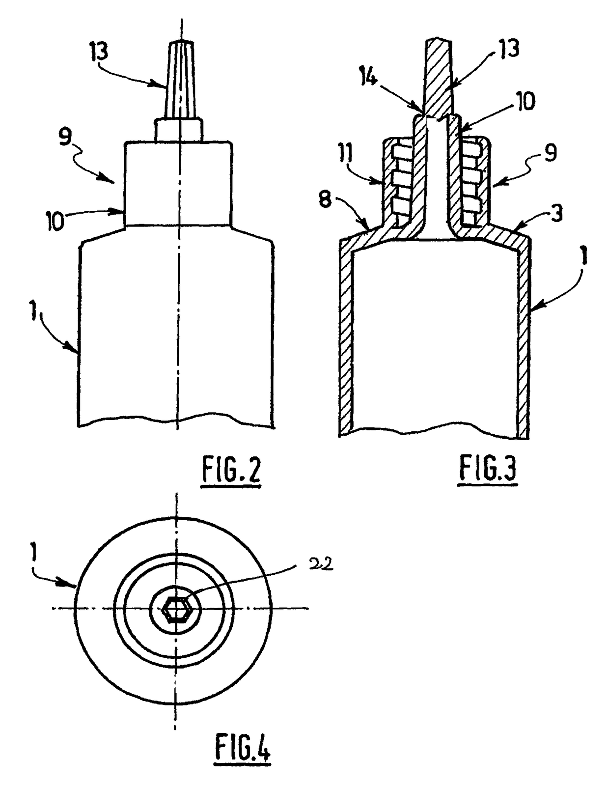
[0056]A hypodermic syringe according to the invention is shown in FIGS. 2 to 9, in which the same elements are designated by the same reference numbers as in FIG. 1.

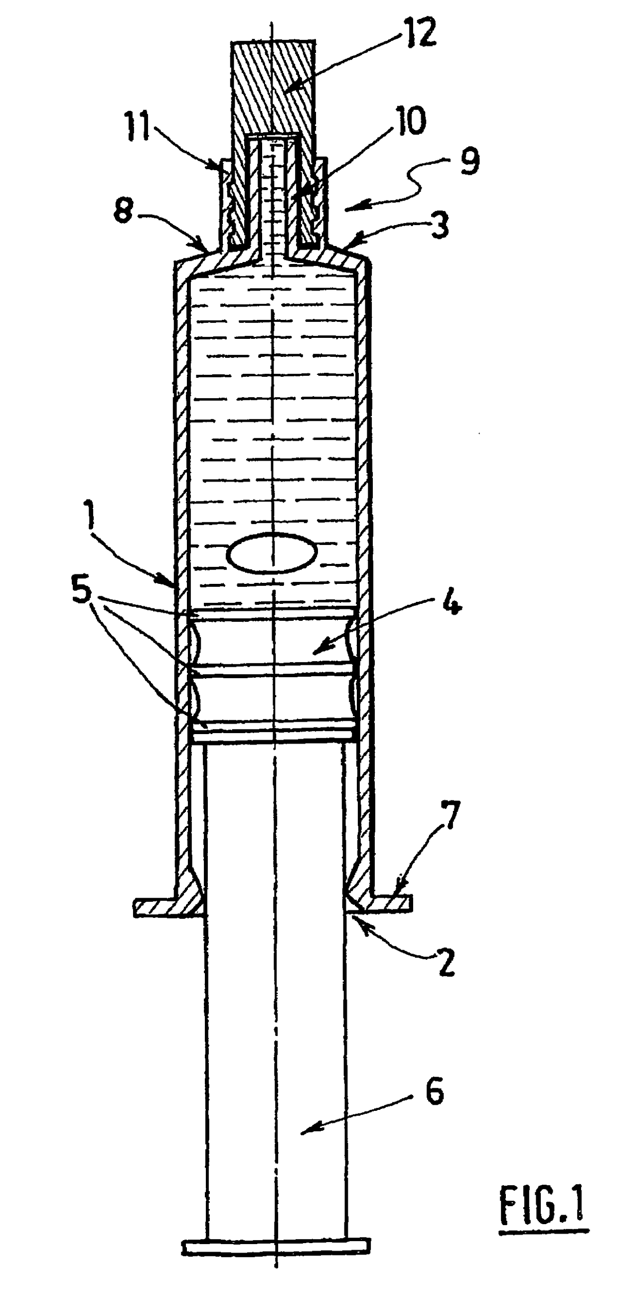
[0057]FIGS. 2 and 3 show a hypodermic syringe which, as is known per se and as has been described previously, comprises a tubular body 1 with an open end 3 at which a tip 9 of the Luer lock type 9 is arranged.

[0058]The tip 9 comprises a tubular part 10 communicating with the opening of the wall 8, and an obturator 13 connected via a frangible zone to the free end of the tubular part 10.

[0059]The tubular body, the tip and the obturator are made of synthetic material and are produced in one piece by molding.

[0060]The frangible zone 14 between the tubular part 10 and the obturator 13 is formed by an annular thinning of the material along the line of connection between the free end of the tubular part 10 and the obturator 13. This makes it possible to separate these two parts, since the thinned area has a low resistance to t...


PUM


Abstract

A pre-filled hypodermic syringe includes a tubular body having two open ends and containing a fluid to be administered to a patient; a plunger which, having at one of its ends a piston mounted to slide in the tubular body, passes through the opening of the first end of the tubular body; a tip for connection in the form of a cone of the Luer or Luer-Lock type, for example for connecting to a needle or to a drip, intended to pass the fluid that is to be administered and comprising a tubular part communicating with the opening of the second end; the tip comprising an obturator connected by a frangible region to the free end of its tubular part, the syringe being made of a synthetic material and obtained by molding, the obturator being molded as one piece with the tip and the tubular body.

Description

BACKGROUND OF THE INVENTION AND DESCRIPTION OF THE PRIOR ART[0001]The invention relates to a pre-filled hypodermic syringe fitted with a stoppering device.[0002]Pre-filled syringes are provided in the form of a standard syringe whose outlet end has a tip fitted with a removable stopper which is mounted sealingly thereon.[0003]FIG. 1 shows such a pre-filled hypodermic syringe. The latter comprises a tubular body 1 with a generally cylindrical shape. This tubular body has a first open end 2.[0004]A plunger 6 passes through the opening of the first end 2 of the tubular body 1. At its end mounted in the tubular body 1, the plunger 6 has a piston 4 which is able to slide inside the tubular body 1 in the longitudinal direction thereof. The plunger 6 thus allows the user to move the piston in translation.[0005]The outer surface of the tubular body 1 has a flange 7 at the first end 2. The user's fingers are placed on the flange, and the piston 4 can be actuated by pressing on the end of the...

Claims


Application Information

Patent Timeline
Patent Type & Authority Patents(United States)
IPC IPC(8): A61M5/24
CPCA61M5/3134A61M5/5086A61M5/347Y10S604/905A61M2005/312
Inventor FREZZA, PIERRE
Owner LAB AGUETTANT SA
Learn More