Orthopedic device for an articular joint

a technology for articular joints and orthopaedic devices, which is applied in the field of orthopaedic devices, can solve the problems of aggravating the risk of disassembly of prosthetic components, and achieve the effect of ensuring the mechanical stability of the orthopaedic device and avoiding the unscrewing of the fixing screw

Active Publication Date: 2012-02-21
TORNIER SA SAINT ISMIER
View PDF12 Cites 23 Cited by
  • Summary
  • Abstract
  • Description
  • Claims
  • Application Information

AI Technical Summary

Benefits of technology

[0005]The invention is intended more particularly to overcome such disadvantages by providing a new component of an articular prosthesis wherein undesirable unscrewing of the fixing screw may be avoided. Owing to the invention, the locking assembly prevents the screw from becoming loose in an inadvertent manner which ensures the mechanical stability of the orthopedic device. The locking assembly is effective even if the fixing screw is not screwed completely into the corresponding threaded hole.
[0017]A spacer may be arranged between the anchor stem and the metaphyseal portion, the spacer being provided, at its opposing faces directed towards the anchor stem and the metaphyseal portion, respectively, with reliefs which are intended to come into engagement with corresponding reliefs which are provided on the anchor stem and the metaphyseal portion, respectively, preventing rotation of the metaphyseal portion relative to the anchor stem about a longitudinal axis of the spacer.
[0018]The invention also relates to an articular prosthesis, particularly a shoulder prosthesis, which comprises an orthopedic device as set out above. Such a prosthesis is more reliable and easier for a surgeon to install than those in the prior art.

Problems solved by technology

If the screw is not tightened sufficiently during the positioning of the prosthesis, the risk of disassembly of the prosthetic component is aggravated.

Method used


Image

  • Orthopedic device for an articular joint
  • Orthopedic device for an articular joint
  • Orthopedic device for an articular joint

Examples


Embodiment Construction

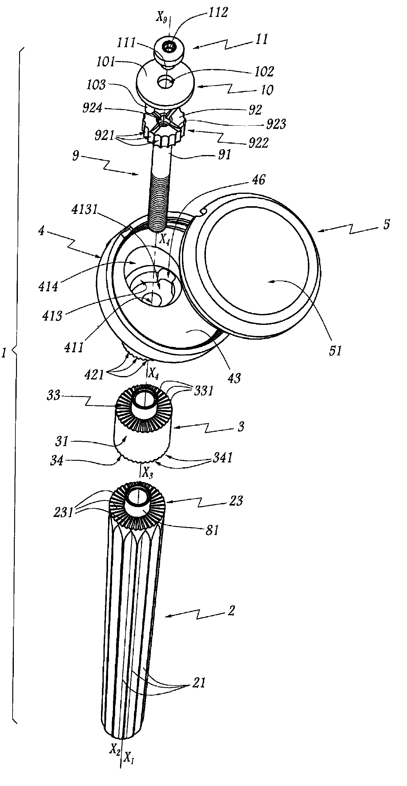
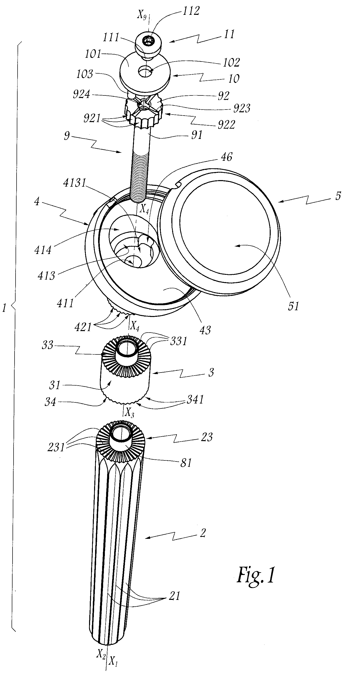
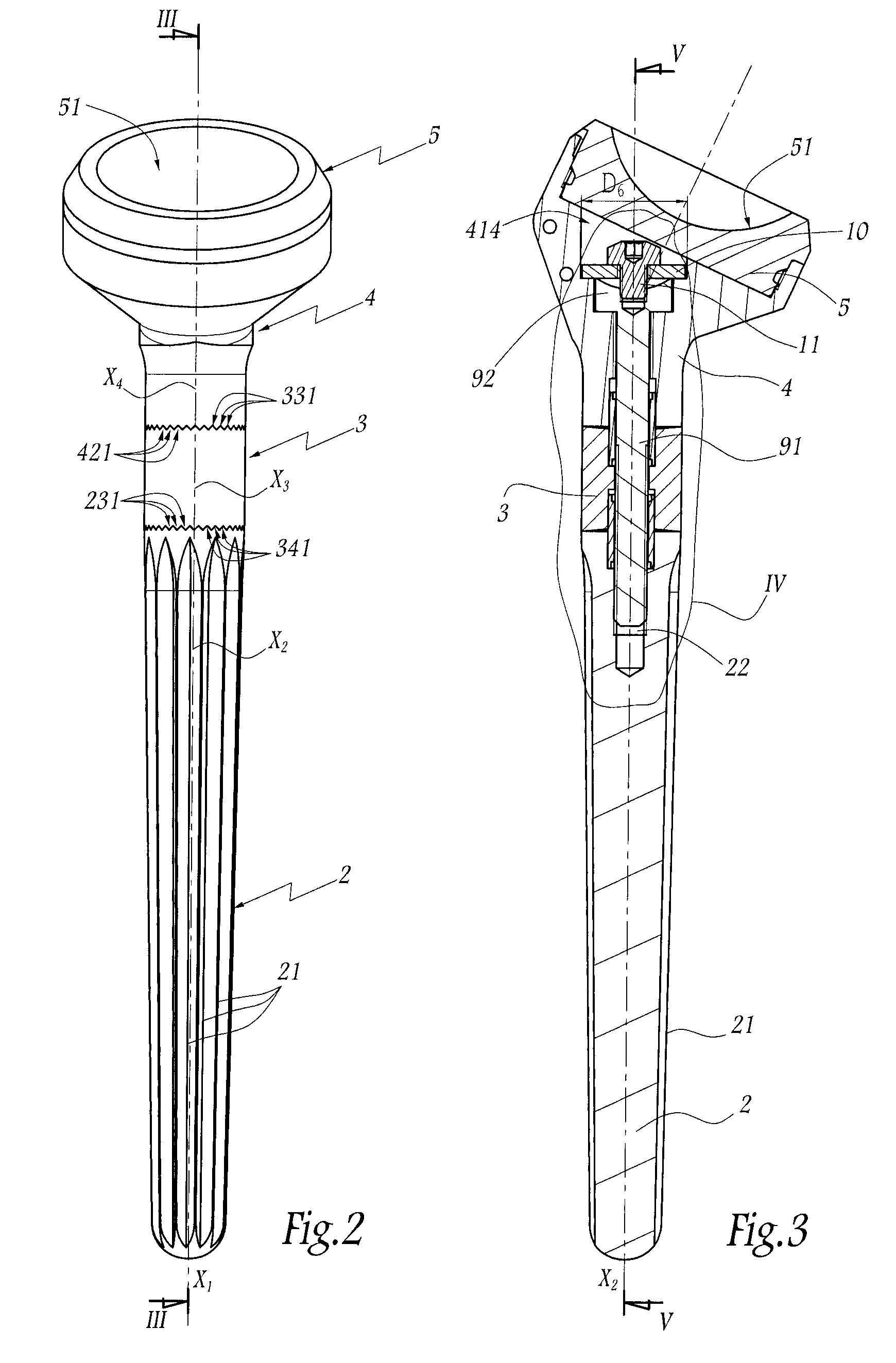
[0050]The humeral orthopedic device 1 of a shoulder prosthesis illustrated in FIGS. 1 to 6 comprises an anchor stem 2 which is intended to be introduced and anchored in the medullary canal of a humerus, after resection of its upper end. The stem 2 is provided with external channels 21 which are intended to facilitate its immobilisation in terms of rotation inside the medullary canal. The stem 2 is provided with an axial threaded hole 22 which extends along the longitudinal axis X2 thereof.

[0051]The orthopedic device 1 also comprises a spacer 3 which is intended to allow longitudinal adjustment of the orthopedic device 1 taking into consideration the morphology of the patient and the fitting depth of the stem 2 in the humeral medullary canal. The spacer 3 may be selected from a set of spacers having different lengths and different diameters.

[0052]The spacer 3 has a cylindrical external radial wall 31 having a circular base. The spacer 3 also has a central bore 32 whose longitudinal a...


PUM


Abstract

An orthopedic device for ball and socket joint reconstruction. The anchor stem is adapted to be anchored in a medullary canal. A proximal portion of the anchor stem includes a threaded hole oriented along a longitudinal axis thereof. Metaphyseal portion includes a proximal end with recess and a longitudinal bore in fluid communication with the recess, and a distal end adapted to interface with the proximal portion of the anchor stem. An anti-rotation structure is preferably located at an interface of the anchoring stem to the metaphyseal portion to prevent rotation of the anchor stem relative to the metaphyseal portion around the longitudinal axis. A fastener is provided to extend through the longitudinal bore and to engage with the threaded hole on the anchor stem to fix the metaphyseal portion to the anchoring stem. The locking assembly is located in the recess and mechanically couples the head of the fastener to the metaphyseal portion to limit rotation of the fastener relative to the metaphyseal portion. An insert with an articular surface is provided that engages with the proximal end of the metaphysical portion and extends over the recess in the metaphyseal portion.

Description

CROSS REFERENCE TO RELATED APPLICATIONS[0001]The present application claims priority to French application No. 0757675 filed on Sep. 19, 2007.FIELD OF THE INVENTION[0002]The present invention relates to an orthopedic device for reconstruction of an articulating joint. The invention also relates to a method for positioning such an orthopedic device.BACKGROUND OF THE INVENTION[0003]In so far as a prosthesis is installed for a long period of time, it is important to ensure the rigidity and mechanical stability of a prosthesis component. If the screw is not tightened sufficiently during the positioning of the prosthesis, the risk of disassembly of the prosthetic component is aggravated.[0004]EP-A-1 769 050 mentions the principle of locking a screw for controlling the displacement of a wedge-like ring which dilates a widened portion of an anchor stem of a prosthesis. This arrangement is specific to locking by means of a wedge-like ring. The means allowing such locking to be obtained are ...

Claims


Application Information

Patent Timeline
Patent Type & Authority Patents(United States)
IPC IPC(8): A61F2/40
CPCA61F2/4014A61F2/36A61F2/38A61F2/4059A61F2002/4022A61F2002/4051A61F2002/4062A61F2002/407
Inventor ROLLET, VINCENT
Owner TORNIER SA SAINT ISMIER
Why Eureka
Try Eureka