
Armature support structure of starter for automotive engine

a technology of armature support and starter, which is applied in the direction of magnetic circuit shape/form/construction, electric generator control, magnetic circuit rotating parts, etc., can solve the problems of increasing conflicting with the reduction of manufacturing costs of starters, and changing air gaps, so as to avoid an increase in reduce the production cost of starters, and reduce the effect of component parts

Inactive Publication Date: 2005-08-16
DENSO CORP
View PDF14 Cites 7 Cited by
  • Summary
  • Abstract
  • Description
  • Claims
  • Application Information

AI Technical Summary

Benefits of technology

[0008]It is another object of the invention to provide a light weight and low cost structure of a starter for internal combustion engines designed to ensure a desired operation of the starter without undesirable mechanical vibrations and / or magnetic noises.
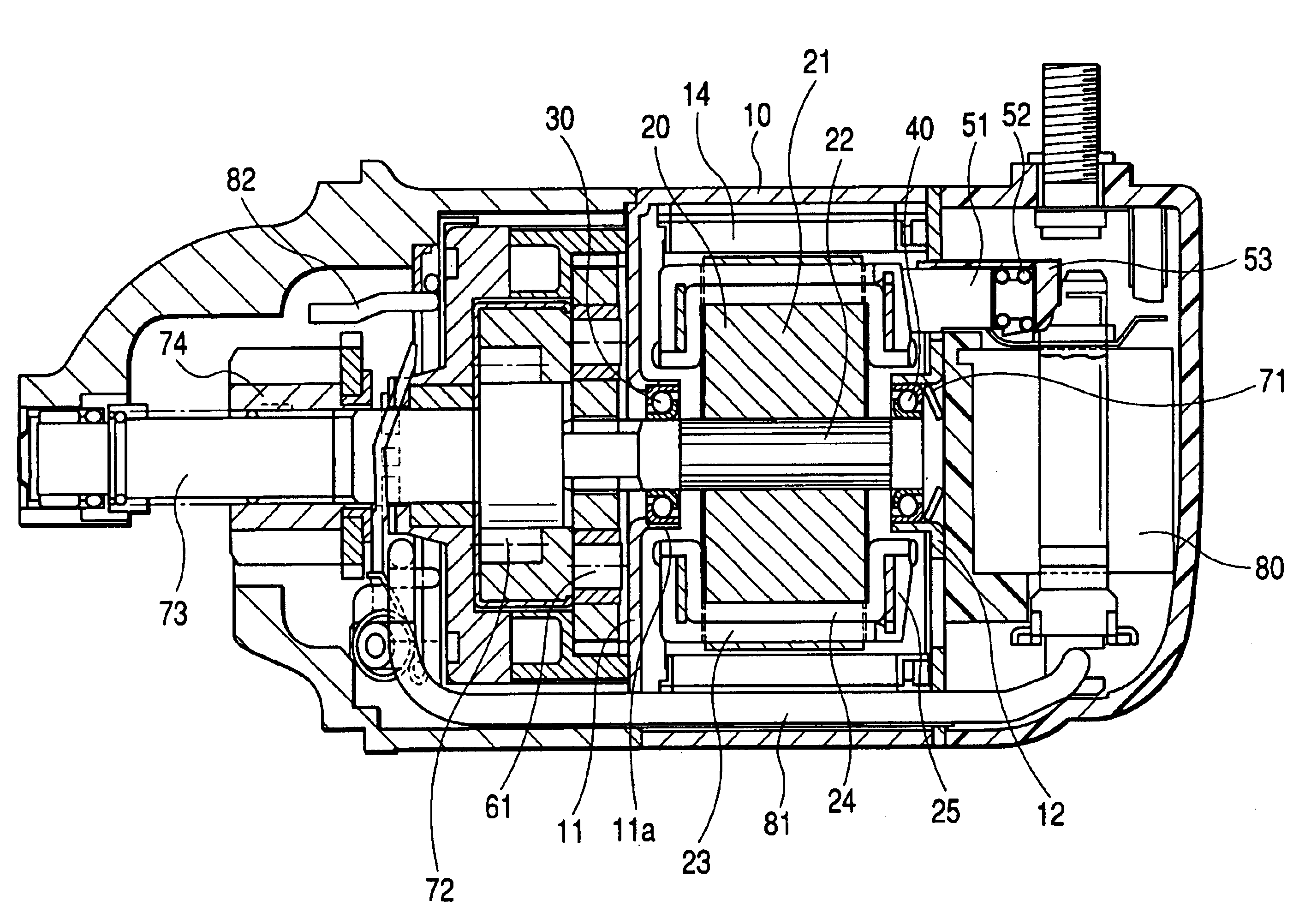
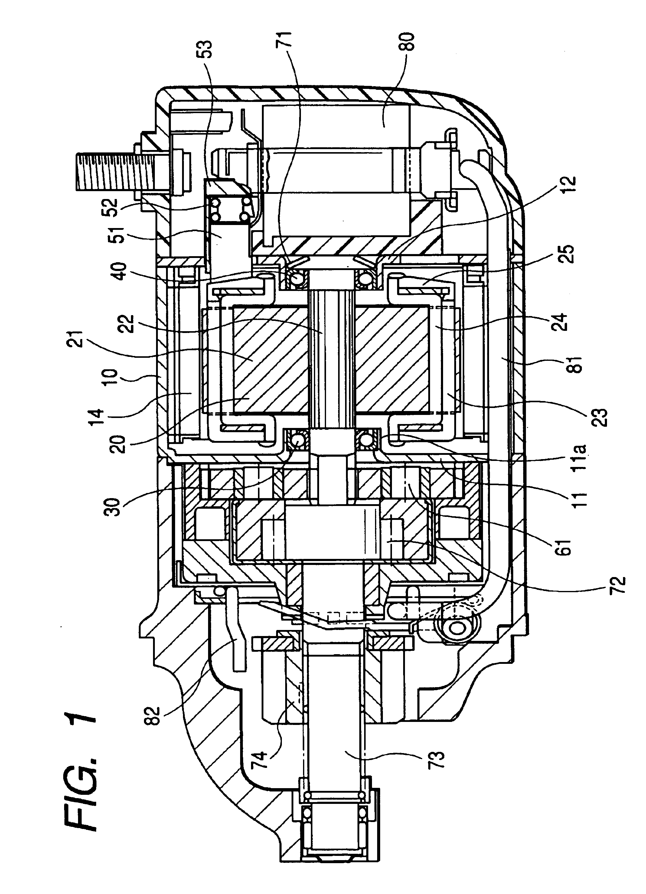
[0018]The starter further includes a cylindrical yoke, frames, and a brush holder. The yoke includes magnetic poles made of permanent magnets or electromagnets. The frames are so disposed on sides of the yoke as to surround the armature. The planetary reduction mechanism and the brushes are installed outside the frames and the yoke. Specifically, only the yoke and the frames are used to retain the bearings firmly, thus ensuring mechanical stability of the armature.

Problems solved by technology

In recent years, demands for light weight, compact, and low cost structures of automotive starters have been getting severe all the more.
The above, however, conflicts with reduction in manufacturing cost of the starters.
The omission of the balancing operation will result in deflection of the armature shaft and vibrations of bearings during rotation of the motor, which leads to a change in air gap in the motor, thus resulting in mechanical and magnetic noises of the motor and wear of the bearings.
This requires the need for balancing the armature in a conventional manner, thus resulting in a difficulty in reducing the manufacturing costs.

Method used


Image

  • Armature support structure of starter for automotive engine
  • Armature support structure of starter for automotive engine
  • Armature support structure of starter for automotive engine

Examples


Embodiment Construction

[0026]Referring to the drawings, wherein like reference numbers refer to like parts in several views, particularly to FIG. 1, there is shown a starter according to the invention which may be used in starting automotive internal combustion engines.

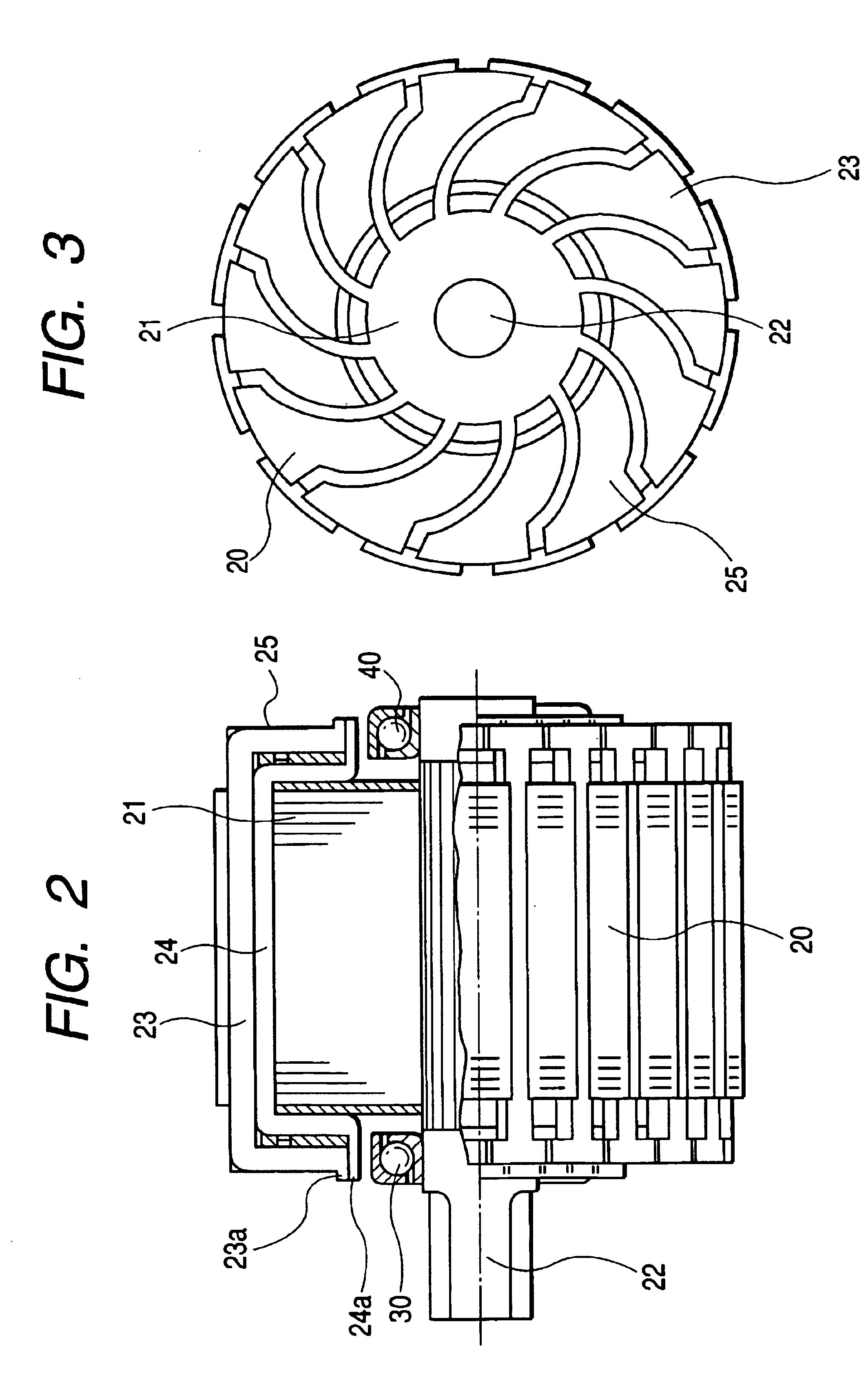
[0027]The starter includes an armature 20 which consists of a core 21, an armature shaft 22, outer coils 23, and inner coils24. The core 21 is made of a laminate of plates and affixed to the armature shaft 22 in a known manner. The outer and inner coils 23 and 24 are, as clearly shown in FIGS. 3 and 4, disposed in grooves formed in the periphery of the core 21, respectively. The outer and inner coils 23 and 24 are, as clearly shown in FIG. 2, of a substantially C-shape and joined together at ends 23a and 24a to form a winding as a whole.

[0028]The outer coils 23 define an end surface 25 which works as a surface commutator to perform commutation together with brushes 51.

[0029]The stator also includes angular contact ball bearings 30 and 40 wh...


PUM


Abstract

A starter for an internal combustion engine is provided which includes a pair of angular contact ball bearings used to support an armature shaft. The bearings are disposed close to opposed ends of a core of an armature. The core has disposed thereon coils which define a commutator on one of the ends of the core. One of the bearings is disposed within an inner periphery of the commutator. This structure results in a decreased interval between the bearings, thus ensuring stability in supporting the armature shaft during rotation, which results in decreased mechanical vibrations, magnetic noises, and wear of the bearings.

Description

BACKGROUND OF THE INVENTION[0001]1. Technical Field of the Invention[0002]The present invention relates generally to a starter working to start internal combustion engines, and more particularly to a support structure for an armature of a motor of such a starter.[0003]2. Background Art[0004]In recent years, demands for light weight, compact, and low cost structures of automotive starters have been getting severe all the more. In order to reduce the size, starters have become prevalent which are equipped with a high-speed motor and a reduction gear working to reduce the speed of the motor to produce an increased torque output, however, there has been an increasing need for a higher reduction gear ratio. This has resulted in an increase in speed of an armature of the motor up to 20000 rpm or more, thus requiring further improvement in balancing the armature mechanically.[0005]The above, however, conflicts with reduction in manufacturing cost of the starters. The omission of the balanc...

Claims


Application Information

Patent Timeline
Patent Type & Authority Patents(United States)
IPC IPC(8): H02K7/08H02K13/00F02N15/02F02N11/00H02K5/173H02K7/10
CPCH02K7/083Y10T74/137H02K13/006
Inventor SHIGA, TSUTOMUNIIMI, MASAMI
Owner DENSO CORP
Learn More