Gas flux determination using airborne DIAL LIDAR and airborne wind measurement

a technology of airborne dial lidar and gas flux determination, which is applied in the direction of liquid/fluent solid measurement, using reradiation, instruments, etc., can solve the problems of difficult and expensive measurement of remote or hard-to-access sites, time-consuming and laborious measurements, and the effect of wasting tim

Active Publication Date: 2012-02-21
HARRIS CORP
View PDF27 Cites 24 Cited by
  • Summary
  • Abstract
  • Description
  • Claims
  • Application Information

AI Technical Summary

Problems solved by technology

Measuring the emissions from these types of sites is made more difficult by the fact that exact sources of emission are not always known.
Many of the conventional techniques for measurement of gaseous emission are ground-based and require long term (several days) access to sites and unobstructed optical paths down-wind of the emission source(s).
Remote or hard to access sites are difficult and expensive to measure.
In addition, measurements are time consuming and take days or weeks to complete as an operator waits for the right wind conditions to direct a plume to a designated optical measurement path.
Because shifts in wind speed and direction result in an ever-changing plume of gas from a site, combining instrument readings from different optical paths over a period of time results in inaccurate flux calculations.
These techniques only allow a partial optical view of ground-hugging plumes, since the instruments are mounted on the tops or sides of vehicles and cannot make measurements fully extending to ground level.
Further, these techniques only allow a near instantaneous (a few seconds at most) snapshot of an entire plume cross section by using a single non-average wind speed and direction when calculating flux.
Accurate wind measurement is a major source of error for these techniques because the wind is constantly shifting.
As a result, pre-positioning retro-reflectors and optical detectors to provide usable flux calculation is largely guesswork and frequently requires subsequent deployment of more ground equipment.
Because of their complexity and time consumption, the cost of using these technologies is high.

Method used


Image

  • Gas flux determination using airborne DIAL LIDAR and airborne wind measurement
  • Gas flux determination using airborne DIAL LIDAR and airborne wind measurement
  • Gas flux determination using airborne DIAL LIDAR and airborne wind measurement

Examples


Embodiment Construction

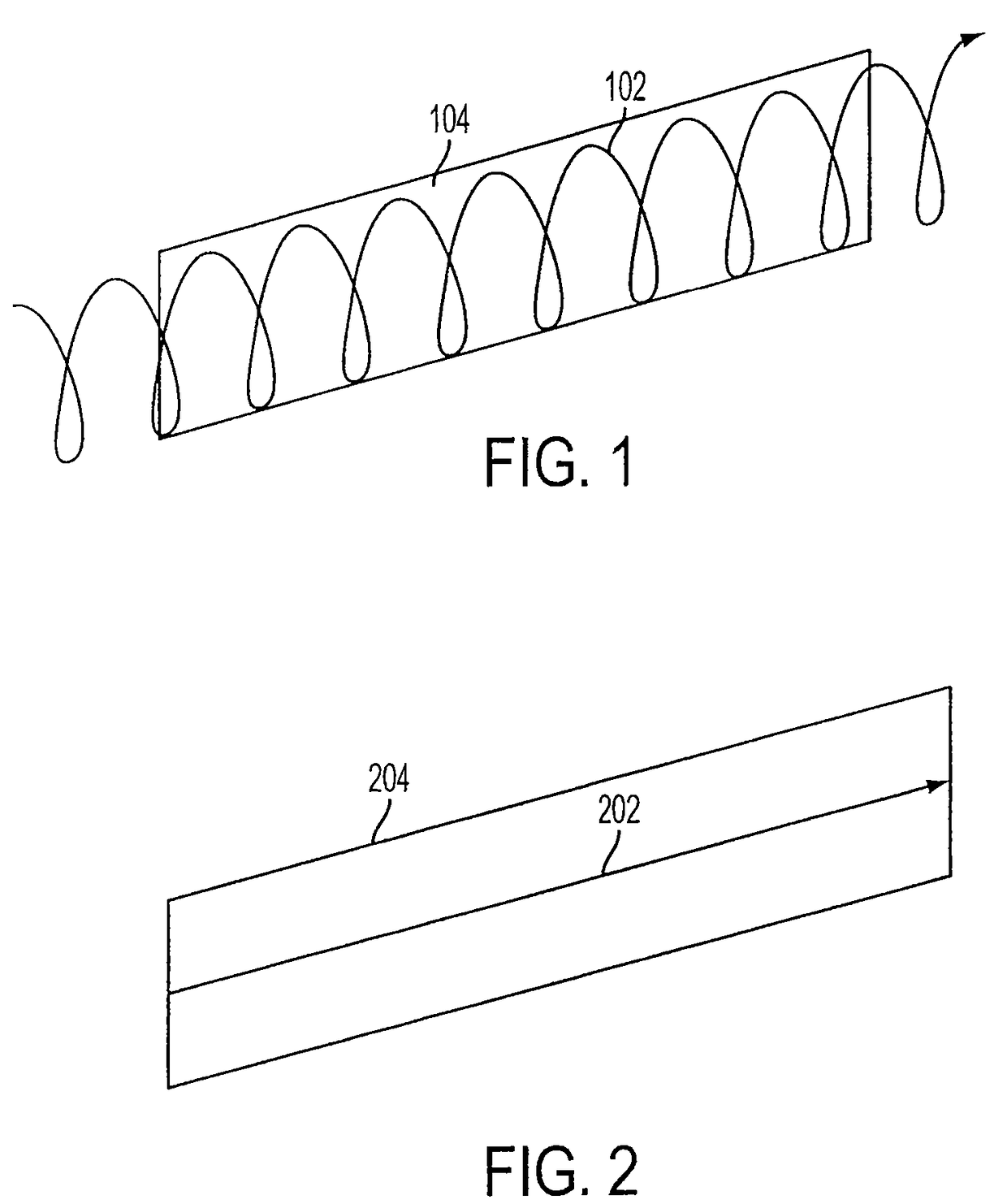
[0051]Referring first to FIG. 1, laser light 102 transmitted from the ANGEL system illuminates target area 104 using a conical scan (scanner-on mode). Alternatively, laser light 202 transmitted from the ANGEL system may illuminate target area 204 in a straight line (scanner-off mode), as shown in FIG. 2. Both modes may be used by the present invention.

[0052]With the exception of deploying lightweight wind sensor instrumentation, the ANGEL system does not need to enter a site to make measurements. The system may fly at high speeds (i.e. 120 mph) and measure large plumes in seconds, in effect providing a snapshot of the plume in time. As a result, measurements taken by the ANGEL system are more accurate than other systems which attempt to quantify a moving plume in several pieces.

[0053]For example, at a flight speed of 120 mph and a transmission rate of 1,000 pulses / second, the pulses are spaced about 2 inches apart providing a “curtain” of gas measurements to fully capture a cross se...


PUM

PropertyMeasurementUnit
horizontal distanceaaaaaaaaaa
altitudeaaaaaaaaaa
altitudeaaaaaaaaaa

Abstract

A system for obtaining emission flux of a gas plume, emanating from a source, includes an airborne differential absorption lidar (DIAL) system for determining multiple concentration path length (CPL) values along a flight path; and an airborne wind measuring system (WMS) for determining a wind vector at the aircraft altitude. Also included is a processor for receiving the multiple CPL values determined by the DIAL system and the wind vector determined by the WMS. The processor uses the CPL values to compute either (a) an area-integrated concentration (AIC) value or (b) an average concentration value over a cross-plume extent, defined along the length dimension of the flight path. The processor also scales the wind vector to the near ground altitude level of the gas plume to obtain a scaled wind vector. The emission flux is obtained by multiplying either the AIC value or the average concentration value with a component of the scaled wind vector. The component of the scaled wind vector is defined by a vector perpendicular to the length dimension of the flight path.

Description

RELATED APPLICATIONS[0001]The present application is a Continuation-In-Part of U.S. patent application Ser. No. 12 / 276,686, filed Nov. 24, 2008, which is incorporated herein by reference in its entirety.FIELD OF INVENTION[0002]The present invention relates, in general, to the field of spectroscopic analysis of a gas plume. More specifically, the present invention relates to determining the emission rate, or flux of a gas plume emanating from a source, by using an aircraft that houses both a differential absorption LIDAR (DIAL) system and a wind measurement system. The present invention improves on the accuracy of the emission rate by scaling the airborne wind measurement from the aircraft's flying altitude to the gas plume's near ground altitude.BACKGROUND OF THE INVENTION[0003]Technologies available for the rate quantification of gas(es) emitted from a point source such as a smokestack or a leaking pipeline are numerous and well understood. These techniques include use of rotameter...

Claims


Application Information

Patent Timeline
Patent Type & Authority Patents(United States)
IPC IPC(8): G01N31/00
CPCG01S17/58G01S17/95Y02A90/10
Inventor LIPPERT, JOSEPH LAWRENCESTEARNS, STEVEN VINCENTBRAKE, DANIEL EVERETTFISHER, CAREN M.
Owner HARRIS CORP
Why Eureka
Try Eureka