Sputtering target with bonding layer of varying thickness under target material

a technology of target material and bonding layer, which is applied in the direction of electrolysis components, vacuum evaporation coatings, coatings, etc., can solve the problems of uneven or non-uniform erosion of sputtering material from the tube, undesirable burn-through, contamination of sputtered film on the substrate, etc., and achieve the effect of reducing the risk of burn-through

Active Publication Date: 2012-02-28
GUARDIAN GLASS LLC
View PDF15 Cites 2 Cited by
  • Summary
  • Abstract
  • Description
  • Claims
  • Application Information

AI Technical Summary

Benefits of technology

[0010]Certain example embodiments of this invention relate to a target for use in sputtering materials onto a substrate. In certain example embodiments, the target comprises a hollow rotatable cathode tube with a bonding layer applied thereto prior to application of the target material to be sputtered onto the substrate. Thus, the bonding layer (which may be of relatively slow sputtering material in certain example embodiments) is located between the cathode tube and the target material to be sputtered, with both the bonding layer and the target material to be sputtered being supported by the cathode tube. The bonding layer is thicker at end portion(s) of the target than at a central portion of the target, so as to reduce the risk of burn-through to the tube during sputtering.
[0011]The use of the slow sputtering material of the bonding layer between the cathode tube and the material to be sputtered is advantageous in that this can reduce the risk of burn-through to or of the tube during sputtering (e.g., in the turn-around area of the target, proximate end portions of the target). In certain example embodiments, the use of the thicker slow sputtering material at end portion(s) of the target may increase the target utilization and / or lifetime of the target. The thickness of the bonding layer is greater proximate end portion(s) of the tube, compared to at a central portion of the tube, since the end portions of the target tend to be high sputtering rate areas proximate the target ends which are sometimes called turn-around areas / portions. The use of thicker bonding layer material at these end portions reduces the risk of burn-through to or of the cathode tube itself. The target material(s) to be sputtered (e.g., Sn, Zn, etc.) can be applied via plasma spraying or the like over the slow sputtering material of the bonding layer. In certain example embodiments of this invention, the bonding layer may be conductive. In certain example embodiments, the bonding layer may extend along the entire, or substantially the entire, length of the target tube, and / or is not exposed during normal sputtering operations.

Problems solved by technology

While rotating magnetron sputtering targets represent an improvement with respect to erosion, they can still experience uneven or non-uniform erosion of the sputtering material from the tube during sputtering—especially at the high sputtering rate areas proximate the target ends which are sometimes called turn-around areas / portions.
Unfortunately, the uneven sputtering of the target material off of the cathode tube can result in undesirable burn-through.
Burning through the target material to the tube 20 would result in the sputtering of material making up the tube (e.g., stainless steel) thereby resulting in contamination of the sputtered film on the substrate.
Thus, it will be appreciated that burn-through to the tube 20 during sputtering represents a significant problem.

Method used


Image

  • Sputtering target with bonding layer of varying thickness under target material
  • Sputtering target with bonding layer of varying thickness under target material
  • Sputtering target with bonding layer of varying thickness under target material

Examples


Embodiment Construction

[0022]Referring now more particularly to the accompanying drawings in which like reference numerals indicate like parts throughout the several views.

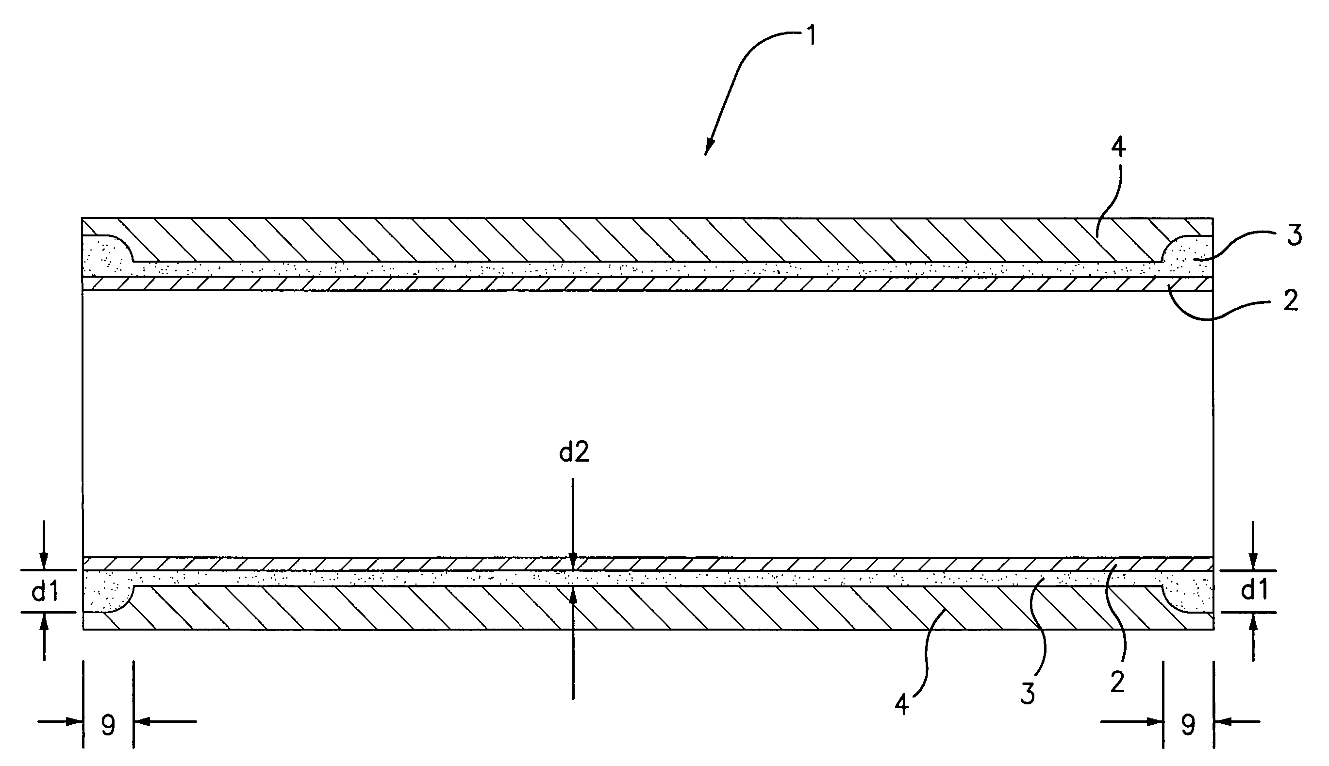
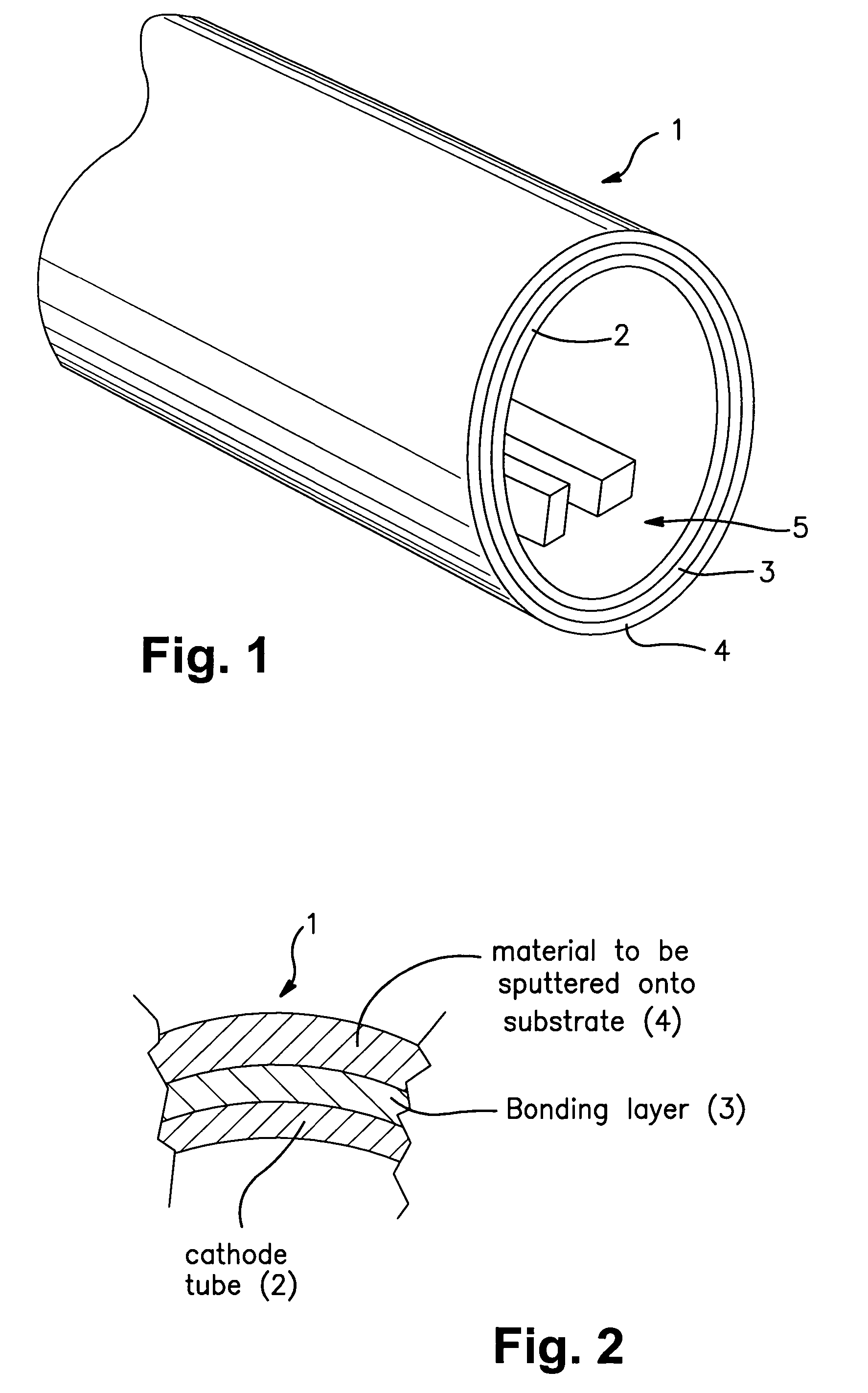
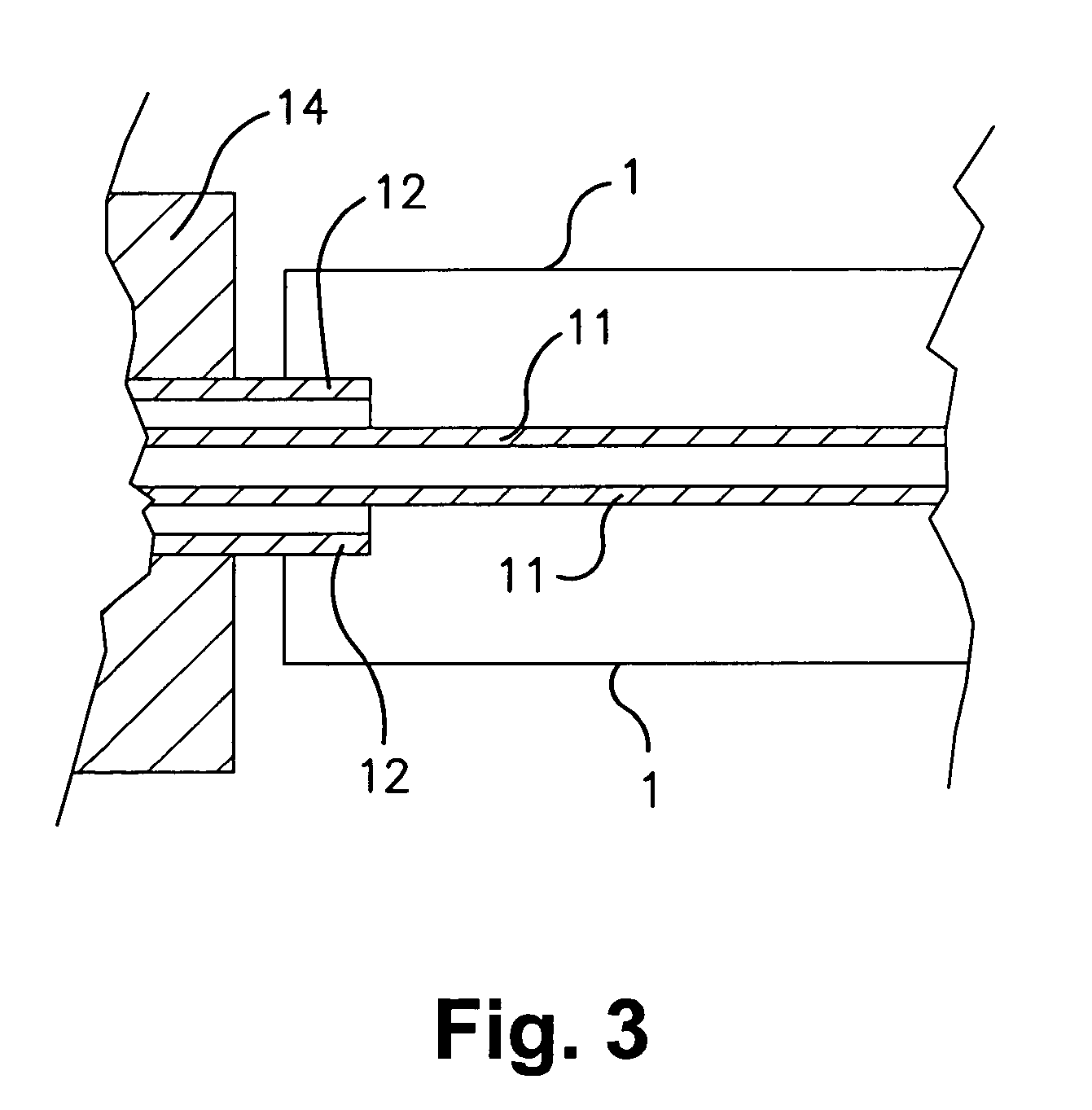
[0023]FIGS. 1-4 illustrate an example sputtering target according to an example embodiment of this invention. FIG. 6 illustrates an example sputtering target according to another example embodiment of this invention, with FIGS. 1-3 being accurate representations of this target as well. The sputtering target 1 in these example embodiments are cylindrical rotatable magnetron type sputtering targets, although other types of targets may also be used. In certain example embodiments of this invention, perhaps as best shown in FIGS. 4 and 6, the thickness of the bonding layer is greater proximate at least one end portion of the target than at a central portion of the target, so as to reduce the likelihood of burn-through to or of the cathode tube during sputtering. FIG. 1 is a perspective view of an end portion of the target, FIG. 2 is an end ...


PUM

PropertyMeasurementUnit
thicknessaaaaaaaaaa
thicknessaaaaaaaaaa
thicknessaaaaaaaaaa

Abstract

Certain example embodiments of this invention relate to a rotatable magnetron sputtering target(s) for use in sputtering material(s) onto a substrate. In certain example embodiments, the target includes a cathode tube with a target material applied thereto via plasma spraying or the like. A bonding layer is provided on the tube, between the cathode tube and the target material. The bonding layer is thicker proximate at least one end portion of the target than at a central portion of the target in order to reduce the likelihood of burn-through to or of the cathode tube during sputtering.

Description

[0001]This invention relates to a target for use in sputtering (e.g., magnetron sputtering), and / or a method of making the same. In certain example embodiments, the cathode tube of the target is coated with a bonding material prior to applying the target material to the tube, where the bonding material is for the purpose of improving the bonding of the target material to the cathode tube. The thickness of the bonding material is of a greater thickness at end portion(s) of the tube than in a central portion of the tube, in order to reduce or eliminate the risk of burn-through to the tube itself during sputtering.BACKGROUND OF THE INVENTION[0002]Sputtering is known in the art as a technique for depositing layers or coatings onto substrates. For example, a low-emissivity (low-E) coating can be deposited onto a glass substrate by successively sputter-depositing a plurality of different layers onto the substrate. As an example, a low-E coating may include the following layers in this ord...

Claims


Application Information

Patent Timeline
Patent Type & Authority Patents(United States)
IPC IPC(8): C23C14/35
CPCC23C14/3407
Inventor MAYER, RAYMOND M.LU, YIWEI
Owner GUARDIAN GLASS LLC
Why Eureka
Try Eureka