Power switching module for battery module assembly

a power switching module and battery module technology, applied in the field of power switching module for battery module assembly, can solve the problems of complex process for assembling mechanical coupling and electrical connection members, increase in the total size of the system, and complex structure of the power switching module, so as to simplify the construction of electrical connection, effectively remove heat generated, and high spatial utilization

Active Publication Date: 2012-02-28
LG ENERGY SOLUTION LTD
View PDF8 Cites 7 Cited by
  • Summary
  • Abstract
  • Description
  • Claims
  • Application Information

AI Technical Summary

Benefits of technology

[0010]Specifically, it is an object of the present invention to provide a power switching module for battery module assemblies, which has an optimum compact arrangement structure in which the power switching module is stably mounted in a limited space of a vehicle while the power switching module has a minimum space occupation, which is easily assembled, and which has a high structural stability against external impacts.
[0034]The battery module assembly according to the present invention may be used as a power source for electric vehicles or hybrid electric vehicles, which have a limited installation space and are exposed to frequent vibration and strong impact, in consideration of the installation efficiency and structural stability of the battery module assembly. Preferably, the battery module assembly according to the present invention is used as a power source for hybrid electric vehicles.

Problems solved by technology

Consequently, when a middle- or large-sized battery module is constructed using a plurality of battery cells, a plurality of members for mechanical coupling and electrical connection between the battery cells are generally needed, and, as a result, a process for assembling the mechanical coupling and electrical connection members is very complicated.
Furthermore, there is needed a space for coupling, welding, or soldering the mechanical coupling and electrical connection members, with the result that the total size of the system is increased.
As a result, the structure of the power switching module is very complicated, and it is difficult to assembly the power switching module.

Method used


Image

  • Power switching module for battery module assembly
  • Power switching module for battery module assembly
  • Power switching module for battery module assembly

Examples


Embodiment Construction

[0044]Now, preferred embodiments of the present invention will be described in detail with reference to the accompanying drawings. It should be noted, however, that the scope of the present invention is not limited by the illustrated embodiments.

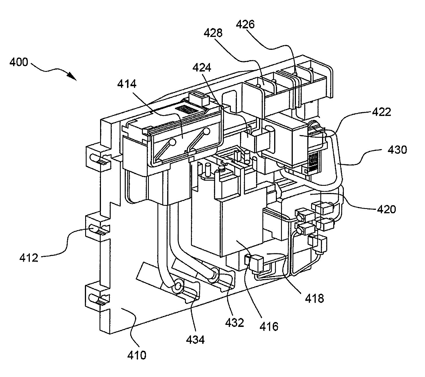
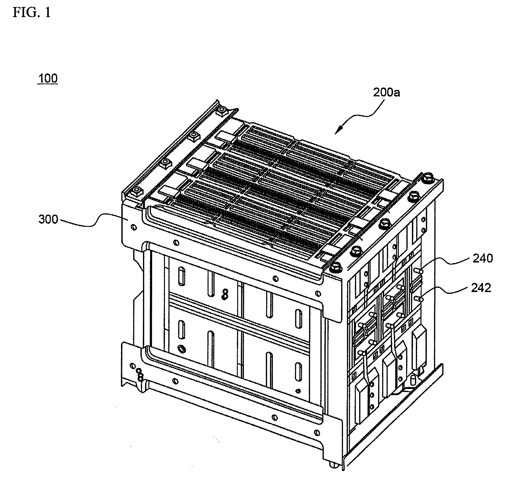
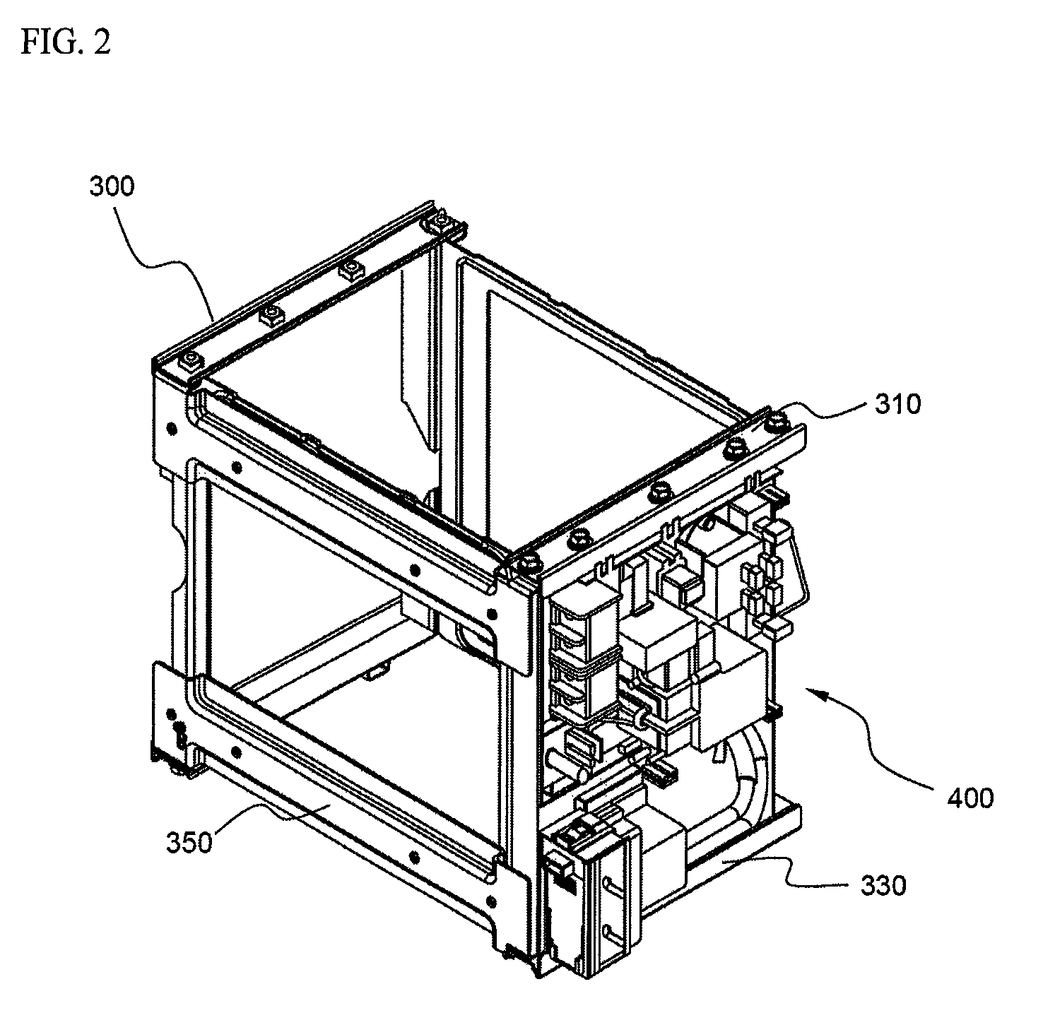
[0045]FIG. 1 is a perspective view typically illustrating a battery module assembly according to a preferred embodiment of the present invention constructed in a structure in which rectangular battery modules, which constitute a hexahedral stack, are fixed by a frame member. For convenience of easy understanding, FIG. 2 is a perspective view typically illustrating a structure in which a power switching module (PSM) is mounted to one side of the frame member while the hexahedral stack is removed from the battery module assembly of FIG. 1. Also, FIG. 3 is a front perspective view typically illustrating the PSM and mounted to one side of the hexahedral stack in the battery module assembly of FIG. 1, and FIG. 4 is a rear perspective view of FIG....


PUM

PropertyMeasurementUnit
voltageaaaaaaaaaa
currentaaaaaaaaaa
resistanceaaaaaaaaaa

Abstract

Disclosed herein is a power switching module for a battery module assembly constructed in a structure in which a plurality of rectangular battery modules, each having a plurality of battery cells or unit modules connected in series to each other, are stacked in the width direction (the longitudinal direction) and the height direction (the transverse direction) by at least twos such that the rectangular battery modules generally constitute a hexahedral structure (hexahedral stack), outer edges of the hexahedral stack are fixed by a frame member, and input and output terminals of the rectangular battery modules are oriented such that the input and output terminals of the rectangular battery modules are directed toward one surface (a) of the hexahedral stack, wherein the power switching module comprises an insulative substrate mounted to the surface (a) of the hexahedral stack in a coupling fashion, elements mounted on the insulative substrate for controlling voltage and current during the charge and discharge of the rectangular battery modules, and connection members mounted on the insulative substrate for interconnecting the control elements.

Description

FIELD OF THE INVENTION[0001]The present invention relates to a power switching module for battery module assemblies, and, more particularly, to a power switching module for a battery module assembly constructed in a structure in which a plurality of rectangular battery modules, each having a plurality of battery cells or unit modules connected in series to each other, are stacked in the width direction (the longitudinal direction) and the height direction (the transverse direction) by at least twos such that the rectangular battery modules generally constitute a hexahedral structure (hexahedral stack), outer edges of the hexahedral stack are fixed by a frame member, and input and output terminals of the rectangular battery modules are oriented such that the input and output terminals of the rectangular battery modules are directed toward one surface (a) of the hexahedral stack, wherein the power switching module comprises an insulative substrate mounted to the surface (a) of the hex...

Claims


Application Information

Patent Timeline
Patent Type & Authority Patents(United States)
IPC IPC(8): H02J7/00H01M50/209H01M50/211H01M50/244H01M50/264H01M50/296H01M50/503H01M50/51
CPCB60K6/28H01M2/206H01M2/1077H01M2/0245Y02E60/10H01M50/258H01M50/209H01M50/264H01M50/51H01M50/296H01M50/503H01M50/211H01M50/244H01H50/02H01H45/02H01H50/00
Inventor YOON, JUNILLRO, JONG-YULYANG, HEEKOOKYOON, JONGMOONJUNG, DO YANG
Owner LG ENERGY SOLUTION LTD
Why Eureka
Try Eureka