Capacitive sensing device and method

a sensing device and capacitive technology, applied in the direction of pulse technique, instruments, transportation and packaging, etc., can solve problems such as power consumption, and achieve the effects of improving determination speed, reducing device power consumption, and improving determination speed

Active Publication Date: 2012-02-28
RENESAS ELECTRONICS CORP
View PDF15 Cites 1 Cited by
  • Summary
  • Abstract
  • Description
  • Claims
  • Application Information

AI Technical Summary

Benefits of technology

[0010]In the capacitive sensing device for sensing changes in capacitances of the electrodes which are caused by contact with the human body, the present invention is useful to improve a determination speed and to realize the reduction in device power consumption which is achieved by the improvement of the determination speed.

Problems solved by technology

Therefore, the measurement takes a certain time, thereby consuming power.

Method used


Image

  • Capacitive sensing device and method
  • Capacitive sensing device and method
  • Capacitive sensing device and method

Examples


first embodiment

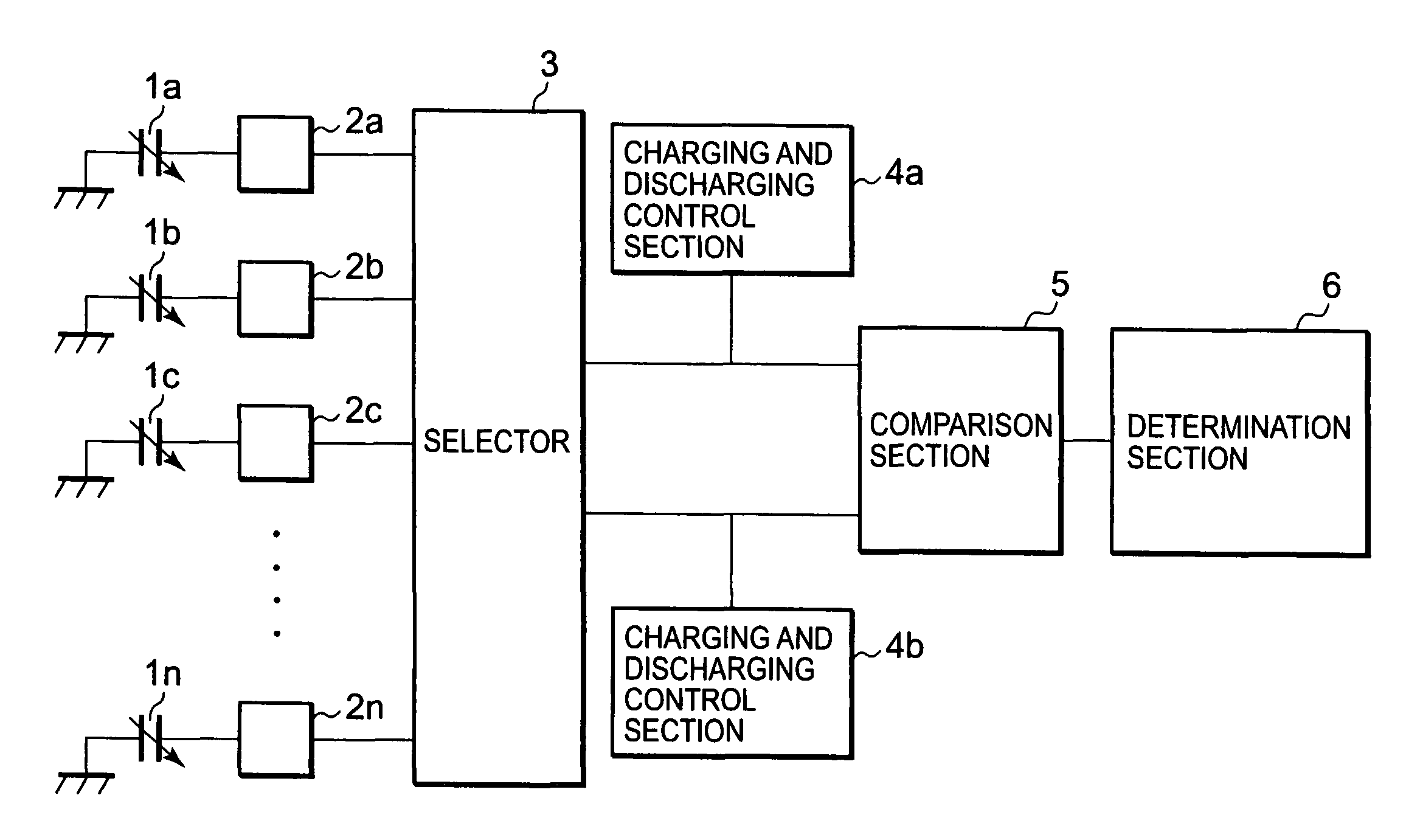
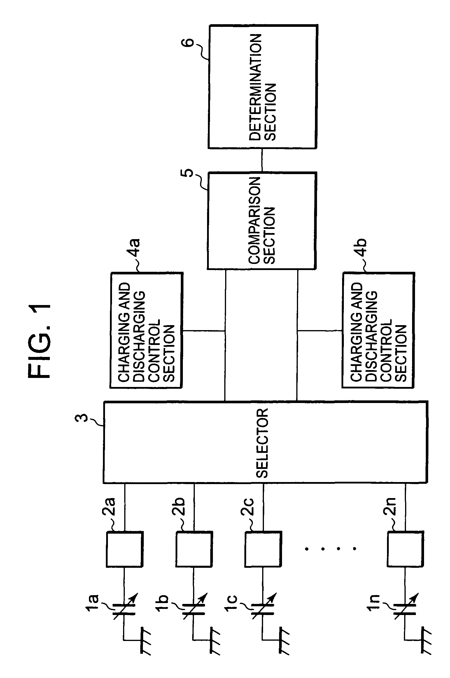
[0027]FIG. 1 is a general explanatory diagram illustrating a concept of a capacitive sensing device according to a first embodiment of the present invention. The capacitive sensing device includes n channels (electrodes) 2a, 2b, . . . , and 2n, capacitors 1a, 1b, . . . , and 1n changed when a human body (finger) is in contact with electrodes, a selector 3, charging and discharging control sections 4a and 4b, a comparison section 5, and a determination section 6.

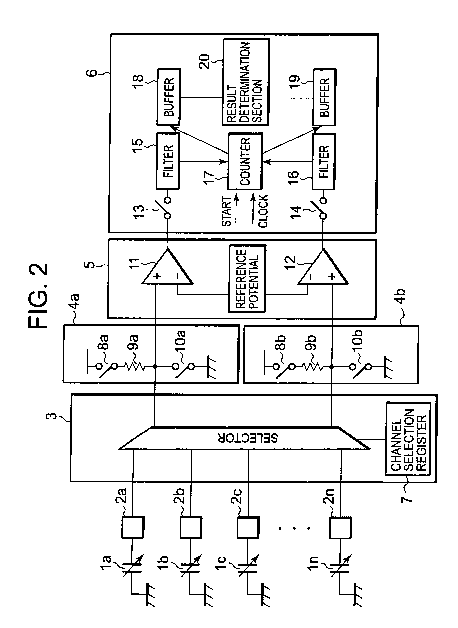
[0028]FIG. 2 is a detailed diagram illustrating the capacitive sensing device. The selector 3 includes a channel selection register 7 for storing a value for selecting two channels of n input channels. The charging and discharging control section 4a (4b) includes a resistor element 9a (9b) and switches 8a and 10a (8b and 10b) for connecting the capacitors 1a to 1n with a power supply potential or a ground potential through the selector 3 to charge or discharge the capacitors 1a to 1n. The comparison section 5 includes compara...

second embodiment

[0048]FIG. 7 illustrates a capacitive sensing device according to a second embodiment of the present invention. The second embodiment is different from the first embodiment in that the determination section 6 includes the counter 17, an exclusive OR (XOR) circuit 21, and latch circuits (storage sections) 22 and 23. As in the first embodiment, the capacitive sensing device may be realized using the microcomputer and the control program as illustrated in FIG. 6 even in the second embodiment.

[0049]Next, an operation of the capacitive sensing device according to the second embodiment is described with reference to FIGS. 7 to 9. Two channels (channels 2a and 2b) are selected from the n input channels by the selector 3 (Step S21). During the interval between the times t1 to t2, the switches 10a and 10b of the charging and discharging control sections 4a and 4b are kept ON (Steps S22 and S23). Then, the capacitors connected to the channels 2a and 2b are discharged.

[0050]At the time t3, the...

third embodiment

[0061]FIG. 10 illustrates a capacitive sensing device according to a third embodiment of the present invention. The third embodiment is different from the first and second embodiments in that the determination section 6 includes the counter 17, the latch circuits (storage sections) 22 and 23, and a compare register 24. As in the first and second embodiments, the capacitive sensing device may be realized using the microcomputer and the control program as illustrated in FIG. 6 even in the third embodiment.

[0062]Next, an operation of the capacitive sensing device according to the third embodiment is described with reference to FIGS. 10 to 12. Two channels (channels 2a and 2b) are selected from the n input channels by the selector 3 (Step S31). During the interval between the times t1 to t2, the switches 10a and 10b of the charging and discharging control sections 4a and 4b are kept ON (Steps S32 and S33). Then, the capacitors connected to the channels 2a and 2b are discharged.

[0063]At ...


PUM


Abstract

In a capacitive sensing device for detecting a change in capacitance of an electrode which is caused by contact with a human body, the improvement of determination speed may be enabled. M (m is an integer satisfying n≧m≧2) electrodes are selected from n (n is an integer equal to or larger than two) electrodes. Capacitors connected to the m electrodes are discharged in parallel during a predetermined period, and then charged. During the charging period, a potential of each of the m electrodes is compared with a reference potential. A difference between capacitance values of the capacitors connected to the m electrodes is determined based on a result obtained by the comparison between the m electrodes.

Description

BACKGROUND OF THE INVENTION[0001]1. Field of the Invention[0002]The present invention relates to a capacitive sensing device and method, and more particularly, to a capacitive sensing device and method for sensing a change in capacitance which is caused by contact with a human body.[0003]2. Description of the Related Art[0004]In recent years, touch sensors for sensing contact with a human body based on a change in capacitance of an electrode are becoming widely popular. For example, the touch sensors are used for, for example, a mobile telephone, a digital music player, and a portable electronic device. The devices need to be driven with a battery, and hence a reduction in power consumption is desired. However, when the change in capacitance is to be sensed, it is normally necessary to charge and discharge a capacitor. Therefore, the measurement takes a certain time, thereby consuming power. Thus, it is necessary for the devices to minimize a time required to sense the change in cap...

Claims


Application Information

Patent Timeline
Patent Type & Authority Patents(United States)
IPC IPC(8): G01R27/26
CPCG06F3/044H03K17/962H03K2217/960715G06F3/04166
Inventor OZAWA, NAOFUMI
Owner RENESAS ELECTRONICS CORP
Why Eureka
Try Eureka