Method and device for adaptive equalization of light transmission system

An adaptive equalization and optical transmission technology, applied in the field of communication, can solve the problems of global minimum point, local minimum point, adaptive equalization of large interference noise, etc., to improve robustness and reliability, The effect of increasing speed

Active Publication Date: 2018-10-16
SANECHIPS TECH CO LTD
View PDF9 Cites 2 Cited by
  • Summary
  • Abstract
  • Description
  • Claims
  • Application Information

AI Technical Summary

Problems solved by technology

However, due to the inherent nonlinear characteristics of algorithms such as CMA, there are not only global minimum points, but also local minimum points.
If the blind equalizer converges to an abnormal state such as a local minimum point instead of a global minimum point, the output of the adaptive equalization will have large interference noise, and the successor module of the coherent receiver will not work normally.
[0006] Aiming at the problem that adaptive equalization converges to a local minimum point instead of a global minimum point in a coherent receiver of a high-speed optical transmission system, in order to speed up the process of the adaptive equalizer finally converging to the working state, no effective solution has been proposed yet

Method used


Image

  • Method and device for adaptive equalization of light transmission system
  • Method and device for adaptive equalization of light transmission system
  • Method and device for adaptive equalization of light transmission system

Examples


example 1

[0090] The adaptive equalizer is an 11-order FIR filter, M=11.

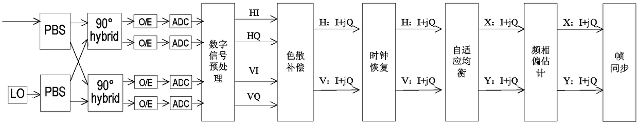
[0091] The process of adaptive equalization of the high-speed optical output system in this example may include:

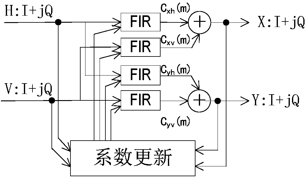
[0092] Step 1, the coefficient update module initially configures the initialization coefficient c of the adaptive equalizer xh (m), c xv (m), c yh (m) and c yv (m); the initial value of the equalizer coefficient is configured as:

[0093] Sequence one: c yv (m)=c xh (m), c xv (m)=c yh (m)=0.

[0094] Initialize the timer and go to step 2.

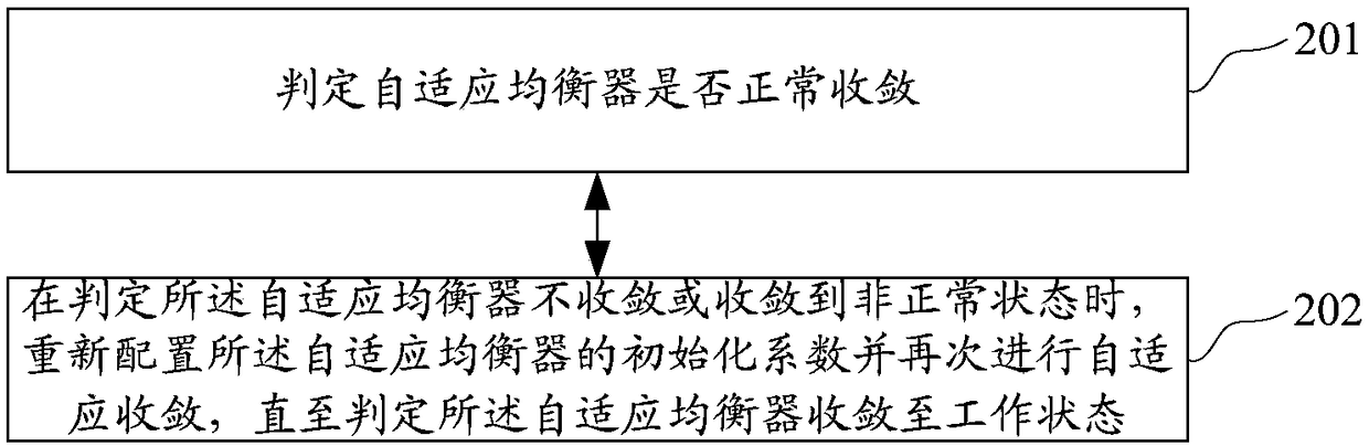
[0095] Step 2, the adaptive equalizer performs adaptive convergence according to the initialization coefficient, and the equalizer convergence monitoring time window T1 is set to [0-50us]. Calculate the mean square error MSE value of the output signal x(n) and y(n) of the equalizer adaptive equalizer with a period of 1us, and set the threshold Th1 to 0.75. If it is less than the set threshold Th1, the adaptive equalizer is considered to be in a conve...

example 2

[0110] The adaptive equalizer is a 19-order FIR filter, M=19.

[0111] In this example, the default filter initial value has the following setting rules:

[0112] Rule one:

[0113] cy v (m)=c xh (m), c xv (m)=cy h (m)=0.

[0114] Rule 2: Set the initialization coefficients of the adaptive equalizer according to the historical values ​​in the coefficient update process, for example, orthogonalize the coefficient corresponding to the signal with a larger MSE as another coefficient.

[0115] The process of adaptive equalization of the high-speed optical transmission system in this example may include:

[0116] Step 1, the coefficient update module initially configures the initialization coefficient c of the adaptive equalizer according to rule 1 xh (m), c xv (m), c yh (m) and c yv (m);

[0117] Initialize the timer and go to step 2.

[0118] In step 2, the adaptive equalizer performs adaptive convergence according to the initialization coefficient, and the equalize...


PUM


Abstract

The invention discloses a method and device for the adaptive equalization of a light transmission system, and the method comprises the steps: judging whether an adaptive equalizer converges normally or not; reconfiguring an initialization coefficient of the adaptive equalizer when the adaptive equalizer does not converge or converges to an abnormal state, and then carrying out the adaptive converging till the adaptive equalizer is judged to converge to a normal state. The method and device can shorten the process that the adaptive equalizer finally converges to a working state.

Description

technical field [0001] The invention relates to the communication field, in particular to a method and device for adaptive equalization of an optical transmission system. Background technique [0002] In high-speed optical transmission systems, coherent receivers need to compensate for various impairments in the optical channel, including polarization mode dispersion (Polarization Mode Dispersion, PMD), chromatic dispersion (Chromatic Dispersion, CD) and polarization dependent loss (Polarization Dependent Loss, PDL) etc. [0003] A coherent receiver structure such as figure 1 As shown, its digital processing part mainly includes modules such as dispersion compensation, clock recovery, adaptive equalization, frequency phase offset estimation, and frame synchronization. The function of dispersion compensation is to compensate the chromatic dispersion in the channel; the function of clock recovery is to solve the clock synchronization problem between the transmitter and recei...

Claims


Application Information

Patent Timeline
Patent Type & Authority Applications(China)
IPC IPC(8): H04B10/61H04L25/03
CPCH04B10/61H04L25/03885
Inventor 陆小凡
Owner SANECHIPS TECH CO LTD
Why Eureka
Try Eureka