
Electronic apparatus

a technology of electronic equipment and coupling mechanism, which is applied in the direction of electrical equipment casings/cabinets/drawers, instruments, applications, etc., can solve the problems of difficult coupling between the main body portion and the display portion, and the position of the display portion cannot be freely adjusted by only the chain mechanism, so as to improve the design of the articulated coupling mechanism and reinforce the coupling mechanism

Inactive Publication Date: 2012-02-28
SONY CORP
View PDF4 Cites 52 Cited by
  • Summary
  • Abstract
  • Description
  • Claims
  • Application Information

AI Technical Summary

Benefits of technology

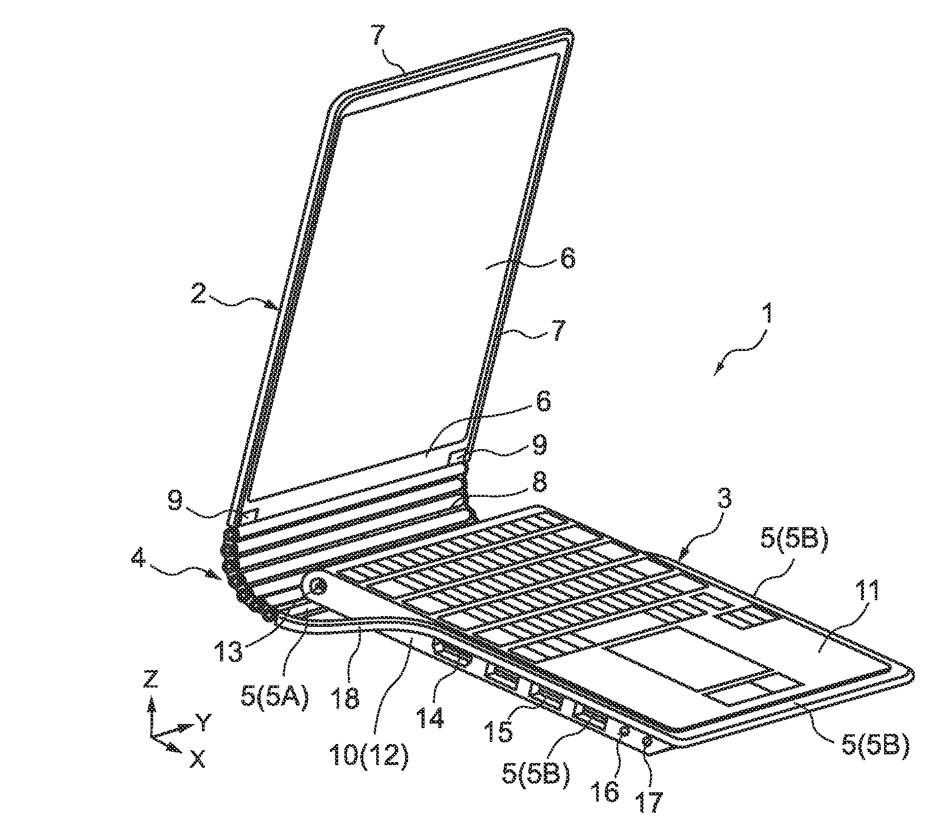
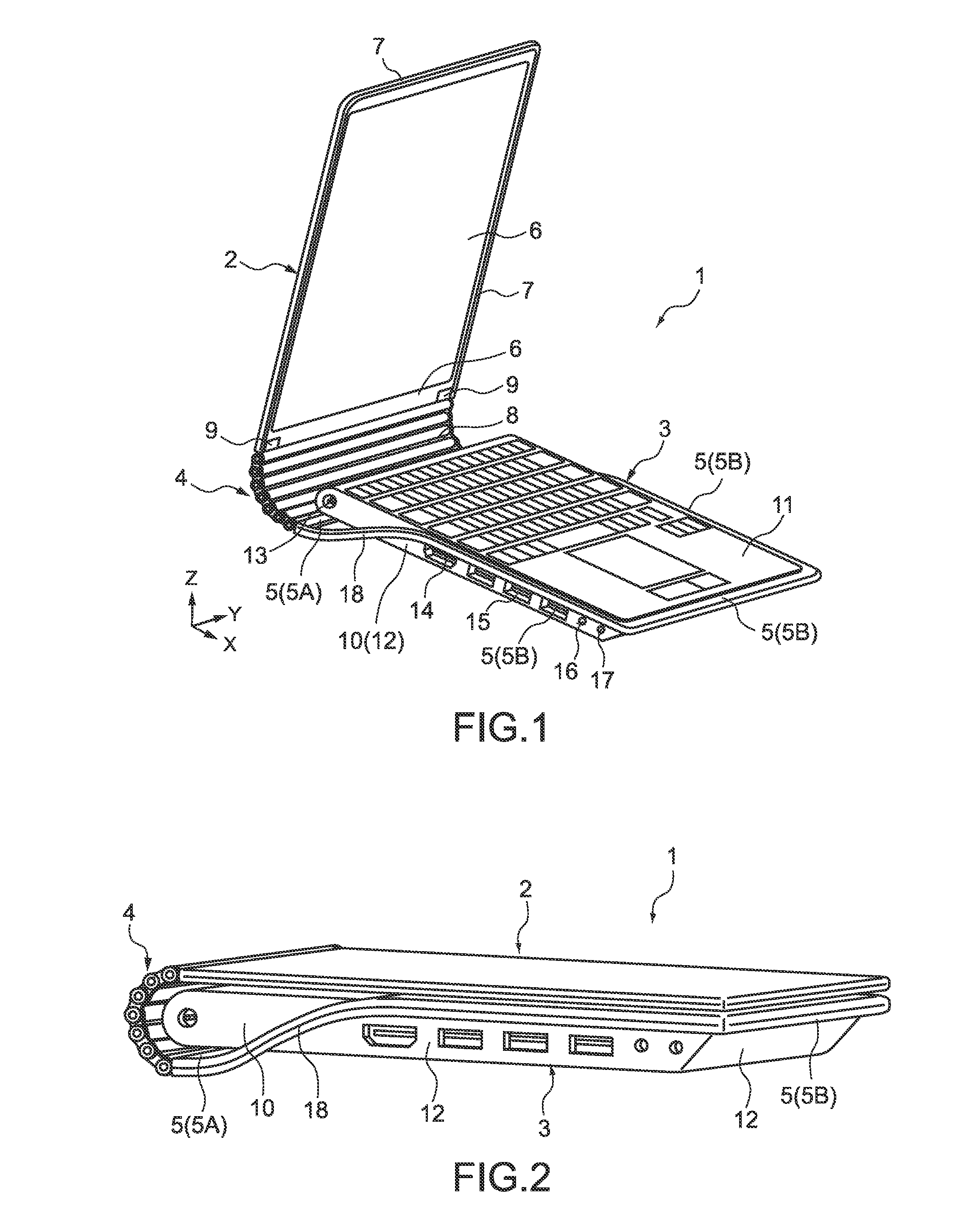
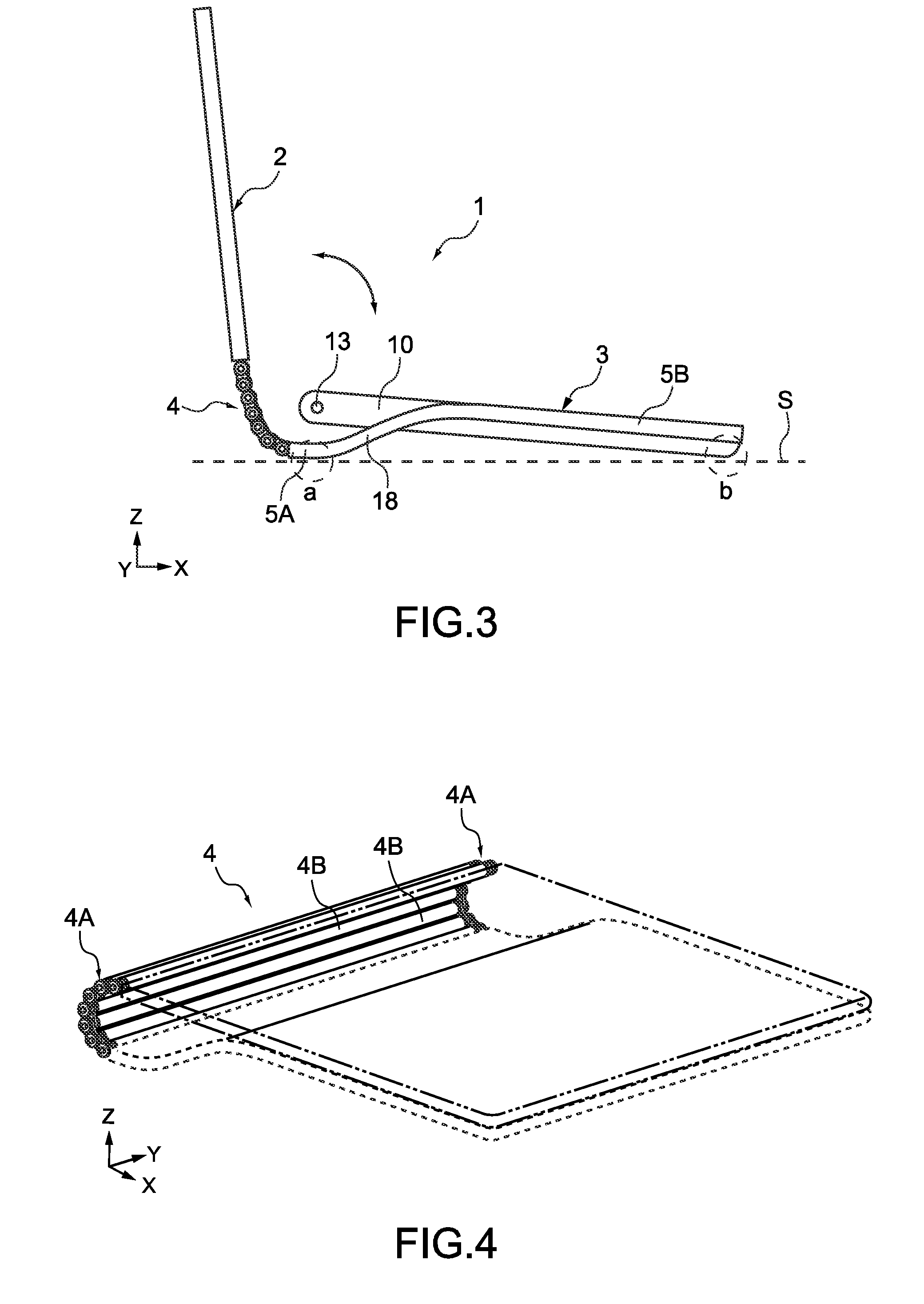
The present invention provides an electronic apparatus with a display portion that can be freely adjusted in position using an articulated coupling mechanism with small axis diameter. The interlock mechanism ensures that the rotations of the coupling members are interlocked with each other, allowing for the position of the display portion to be adjusted by multiple joints. The articulated coupling mechanism may be structured in a zigzag manner or provided in a pair that is away from each other in a width direction of the main body portion. The electronic apparatus may also include a plurality of second coupling members that reinforce the articulated coupling mechanism and improve its design.

Problems solved by technology

However, since the electronic apparatus of Patent Document 1 needs to obtain a torque to hold the position of the display portion with respect to the main body portion by a coupling member such as a hinge, it is difficult to couple the main body portion and the display portion using a coupling member that does not have a certain axis diameter or more.
In other words, the position of the display portion cannot be freely adjusted by only the chain mechanism.

Method used


Image

  • Electronic apparatus
  • Electronic apparatus
  • Electronic apparatus

Examples


second embodiment

[0086]Next, an electronic apparatus according to a second embodiment of the present invention will be described. It should be noted that in the second and subsequent embodiments, components that are the same as those of the first embodiment are denoted by the same reference symbols, descriptions thereof are omitted, and different points will be mainly described.

[0087]FIG. 8 is an enlarged view of an interlock mechanism of an articulated coupling mechanism of the electronic apparatus of the second embodiment.

[0088]In this embodiment, an electronic apparatus 100 is different from the first embodiment in that the electronic apparatus 100 includes an articulated coupling mechanism 60 including cams in place of the articulated coupling mechanism 4 including the gears 41 and the like.

[0089](Interlock Mechanism)

[0090]Coupling plates 61 to 68 of the articulated coupling mechanism 60 are rotatably coupled to one another as described above. The articulated coupling mechanism 60 includes a cam...


PUM


Abstract

An electronic apparatus includes a display portion, a main body portion, an articulated coupling mechanism, and an interlock mechanism. The display portion includes a display screen. The main body portion is coupled to the display portion. The articulated coupling mechanism includes, at each of end portions, a plurality of coupling members each having a rotation axis and being rotatably coupled to one another in series about the rotation axis, the plurality of coupling members coupled in series having one end coupled to the main body portion side and the other end coupled to the display portion side. The interlock mechanism interlocks rotations of the plurality of coupling members with one another in the articulated coupling mechanism.

Description

BACKGROUND OF THE INVENTION[0001]1. Field of the Invention[0002]The present invention relates to an electronic apparatus such as a personal computer and a cellular phone.[0003]2. Description of the Related Art[0004]An electronic apparatus such as a laptop personal computer and a foldable cellular phone includes a main body portion and a display portion, and the main body portion and the display portion are coupled to each other so as to be openable / closable (foldable) via a hinge. Such an electronic apparatus needs to be provided with a coupling member such as a hinge having a certain axis diameter or more in order to obtain a torque to hold a position of the display portion with respect to the main body portion (see Japanese Patent Application Laid-open No. 2008-298278 (paragraph [0023] and FIGS. 1 and 2), for example; hereinafter, referred to as Patent Document 1).[0005]Further, there has been recently known an electronic apparatus as described above, in which the main body portio...

Claims


Application Information

Patent Timeline
Patent Type & Authority Patents(United States)
IPC IPC(8): F23Q3/00
CPCF16G13/18F16M11/40G06F1/1679G06F1/1681F16M11/10F16M13/00H04M1/0216F16M2200/024F16M2200/022
Inventor FUKUMA, YOHEIMORISAWA, RUINAKAMURA, MITSUHIROYONEDA, NAOFUMI
Owner SONY CORP
Learn More