
Robot for cleaning wall/window

a wall/window and robot technology, applied in the field of wall/window cleaning robots, can solve the problems of time-consuming and many problems, and no or less intensive research has been made for developing a method for efficiently cleaning such glass windows and smooth walls

Inactive Publication Date: 2012-03-06
KIM YONG WOOK
View PDF3 Cites 20 Cited by
  • Summary
  • Abstract
  • Description
  • Claims
  • Application Information

AI Technical Summary

Benefits of technology

The robot achieves smooth, spot-free cleaning of walls and windows by preventing water from flowing downwards and allowing for complete coverage, including dead zones, while minimizing the risk of falling and maintaining stability during operation.

Problems solved by technology

Although numerous buildings having glass windows and smooth walls have been constructed for several ten or hundred years, no or less intensive research has been made for developing a method for efficiently cleaning such glass windows and smooth walls.
It, however, involves many problems.
For example, it is time consuming and exposes a person who performs such cleaning task to a danger of falling.
In particular, in case of cleaning a window of an apartment building, water used in the cleaning may flow downwards, thereby causing the water to soil the outer surfaces of windows on the lower stories.
The prior art wall / window cleaning robots, however, still do not solve the above-mentioned problems; for instance, water used in a cleaning operation may flow downwards.
Furthermore, they are so large and heavy that they can be separated from an outer wall / window during cleaning operation.
More seriously, they have a structure that necessarily stops the movement intermittently, thereby leaving undesirable spots after the cleaning operation is completed.
Moreover, they cannot clean a dead zone of the outer wall / window because they need too large a radius of rotation to change their movement direction, resulting in unsatisfactory cleaning.
For various reasons including the above-mentioned problems, no prior art cleaning robots have been successfully practically applied.

Method used


Image

  • Robot for cleaning wall/window
  • Robot for cleaning wall/window
  • Robot for cleaning wall/window

Examples


Embodiment Construction

[0022]Now, preferred embodiments of a wall / window cleaning robot in accordance with the present invention will be described with reference to the accompanying drawings.

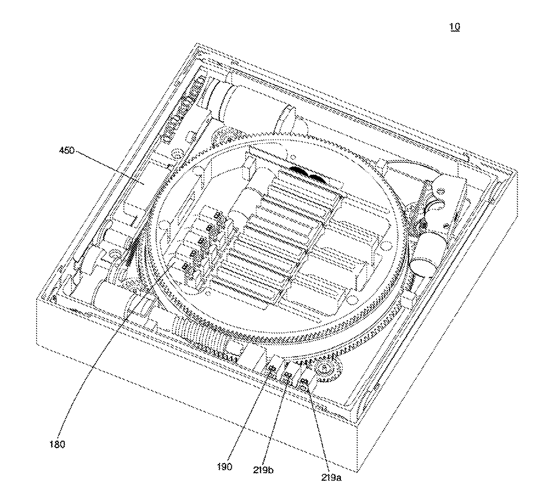
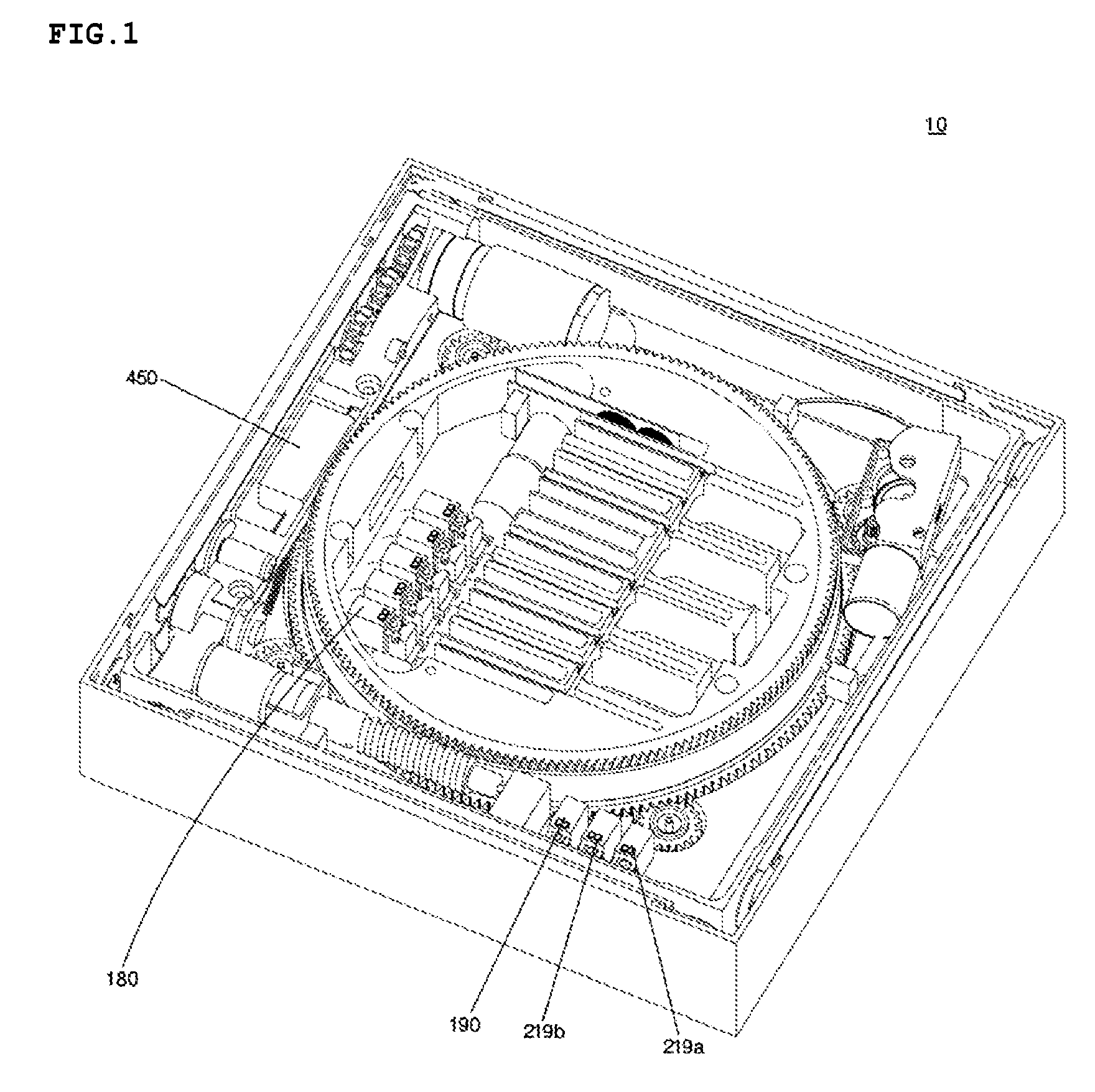
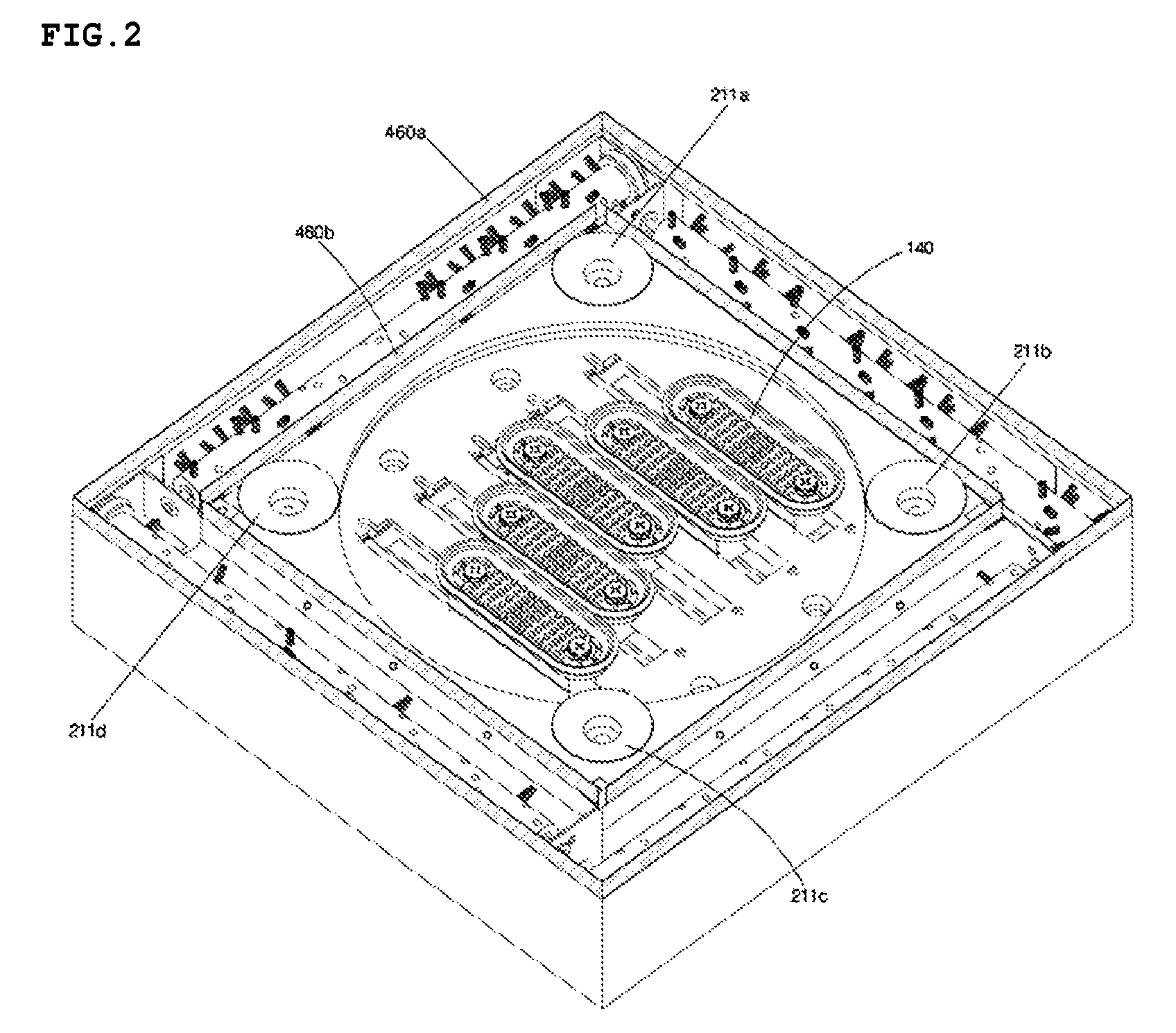
[0023]FIGS. 1 and 2 are perspective views respectively illustrating the top and bottom of the body of a cleaning robot according to a preferred embodiment of the present invention.

[0024]The body 10 of the cleaning robot mainly includes a moving unit for moving the robot in a first direction, a direction changing unit for changing the movement direction of the robot, and a cleaning unit mounted on peripheral area of the body 10. The body 10 is connected to a multi-hose cable 500 (FIG. 6).

[0025]Hereinafter, the configuration and operation of the cleaning robot according to a preferred embodiment of the present invention will be described in conjunction with respective parts of the robot.

[0026]FIGS. 3A and 3B illustrate a moving unit according to a preferred embodiment of the present invention. FIG. 3A is a perspective v...


PUM


Abstract

A robot according to the present invention cleans the outer surface of a window / wall by performing automatic movement along the outer surface of the window / wall while being vacuum-sucked onto the outer surface. The robot includes a moving unit for moving the robot in a first direction, a direction changing unit for rotating the moving unit to change a movement direction of the robot, and a cleaning unit mounted on at least one side of the robot. The robot can prevent water used to clean the window or outer wall of a building from being dropped toward a lower story. Also, the robot can run smoothly so that it can achieve a satisfactory cleaning operation without forming spots. The robot uses a turntable system, so that it can also freely change the movement direction thereof about the center thereof up to 360° without requiring any radius of rotation, to easily approach even a dead zone. The robot has a minimum size and a minimum weight, so that it can minimize the possibility that the robot falls down during a cleaning operation.

Description

CROSS-REFERENCE TO RELATED APPLICATION[0001]This application claims the benefit of Korean Patent Application No. 10-2007-0014014 filed on Feb. 9, 2007, the entire contents of which are incorporated herein by reference.TECHNICAL FIELD[0002]The present invention relates to a wall / window cleaning robot, and more particularly to a wall / window cleaning robot for cleaning the surface of a wall or window by performing automated movement along the surface while being vacuum-sucked onto the surface.BACKGROUND ART[0003]Although numerous buildings having glass windows and smooth walls have been constructed for several ten or hundred years, no or less intensive research has been made for developing a method for efficiently cleaning such glass windows and smooth walls. For this reason, cleaning of glass windows and smooth walls has been done using manual labor.[0004]It, however, involves many problems. For example, it is time consuming and exposes a person who performs such cleaning task to a da...

Claims


Application Information

Patent Timeline
Patent Type & Authority Patents(United States)
IPC IPC(8): G05D1/00B25J9/00
CPCA47L1/02B62D57/024A47L2201/00A47L2201/04B25J1/08A47L9/28
Inventor KIM, YONG WOOK
Owner KIM YONG WOOK
Learn More