
Machined spring with integral retainer for closed cycle cryogenic coolers

a technology of closed cycle and retainer, which is applied in the direction of refrigerating machines, hot gas positive displacement engine plants, lighting and heating apparatus, etc., can solve the problems of inability to prevent re-injection, degrade the useful life of the piston assembly, and inducing hereditary relative motion, so as to reduce the generation of debris and improve the axial stability of the assembly. , the effect of reducing the side load of the clearance seal

Active Publication Date: 2012-03-06
COBHAM MISSION SYST DAVENPORT LSS INC
View PDF26 Cites 24 Cited by
  • Summary
  • Abstract
  • Description
  • Claims
  • Application Information

AI Technical Summary

Benefits of technology

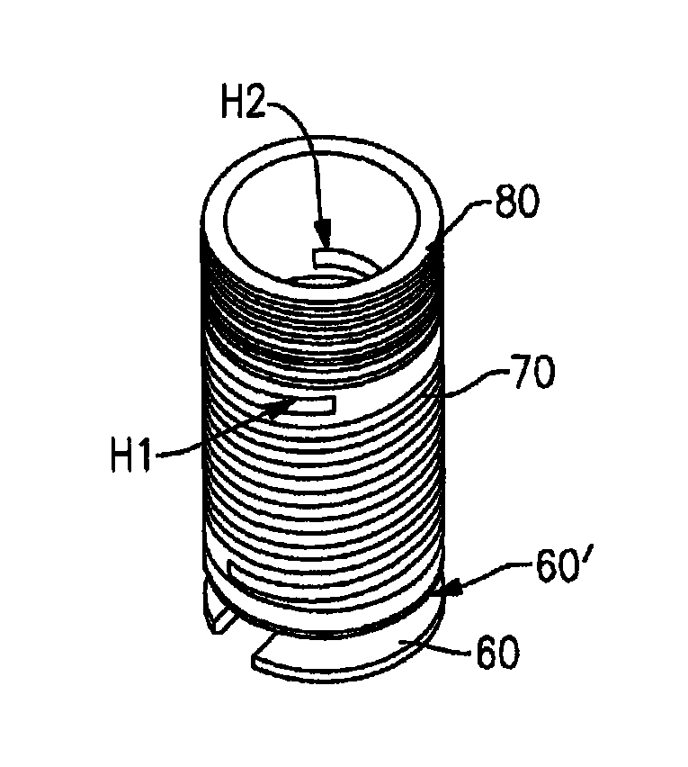
[0006]The present invention satisfactorily reduces the debris generation problems of the prior art by providing a retainer and spring having an integral threaded end, all formed from a single piece of material. In a preferred embodiment, the retainer, spring and threaded end is a unitary part machined from a single piece of metal. The spring is preferably a double-start helix design which greatly improves the axial stability of the assembly through its oscillating movements within the CCCC. Since the spring is formed integrally with the retainer and threaded end in a single piece, these parts cannot rub against each other and debris generation is thus substantially reduced.
[0007]In addition to the elimination of debris, axial translation of the machined spring results in substantially symmetric deflection, thus eliminating intrinsic rotation of the prior art wound spring and thereby reducing clearance seal side loading. This improves both the operating life of the device as well as its efficiency as a CCCC.

Problems solved by technology

A common problem with the traditional three piece spring, piston, and retainer designs used in CCCC applications is the inherent relative motion induced by the wound helical spring threading onto the piston and retainer.
Any off-axis movement has the potential to cause debris due to surfaces rubbing against each other.
Such debris degrades the useful life of the piston assembly and decreases operating efficiency of the CCCC.
None of these approaches have satisfactorily improved the debris generation problem.

Method used


Image

  • Machined spring with integral retainer for closed cycle cryogenic coolers
  • Machined spring with integral retainer for closed cycle cryogenic coolers
  • Machined spring with integral retainer for closed cycle cryogenic coolers

Examples


Embodiment Construction

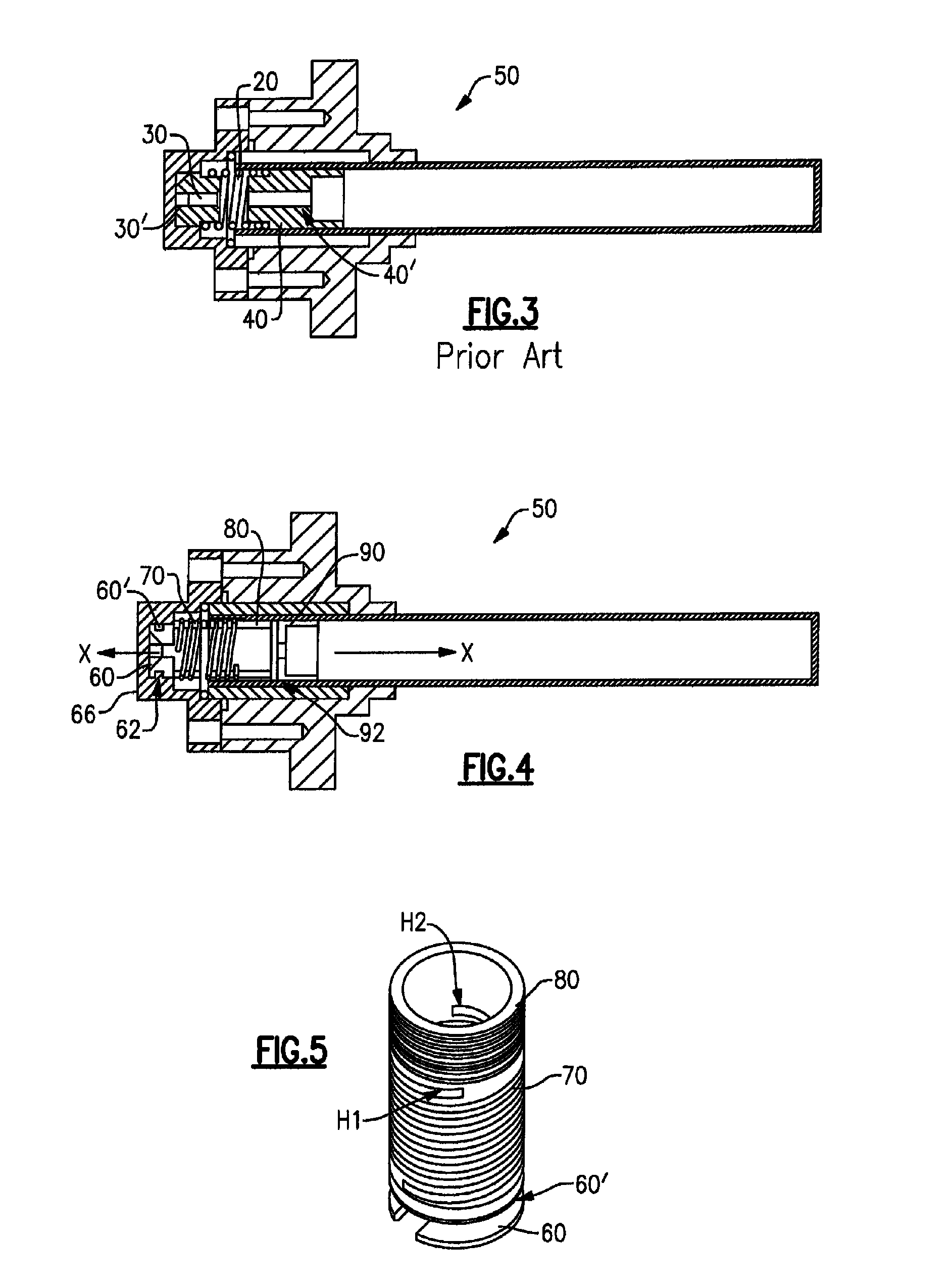
[0013]Referring now to FIGS. 4 and 5, an embodiment of the inventive retainer / spring / threaded end and piston assembly of the invention will now be described. The retainer / spring / threaded end element has three distinct parts machined from a single piece of metal such as stainless steel, for example: a retainer 60, a spring 70, and a threaded end 80 at the end of spring 70 opposite retainer 60, each having a common passageway aligned along axis X-X. Retainer 60 includes a recessed end 60′ which engages a cooperatively formed lip 62 within the CCCC cylinder 66. Threaded end 80 threads into piston 90 which is mounted for reciprocating movement in CCCC expander section 50. As such, during operation of the CCCC, the retainer 60 remains stationary as the piston 90 reciprocates axially (e.g., about 0.050 inch) in each direction under the compression and extension of the spring 70.

[0014]Piston 90 preferably includes a low friction clearance seal 92 bonded thereto as seen in FIG. 4 and descri...


PUM


Abstract

A retainer and spring with threaded end are machined from a single piece of material for threading to a piston in a closed cycle cryogenic cooler. Since the machined retainer and spring are a unitary part, they cannot rub against each other during operation of the piston which reduces debris generation. The spring is preferably formed as a double start helix which further increases axial stability and reduces side loading. The spring extends into an integrally formed, threaded end at the end thereof opposite the retainer.

Description

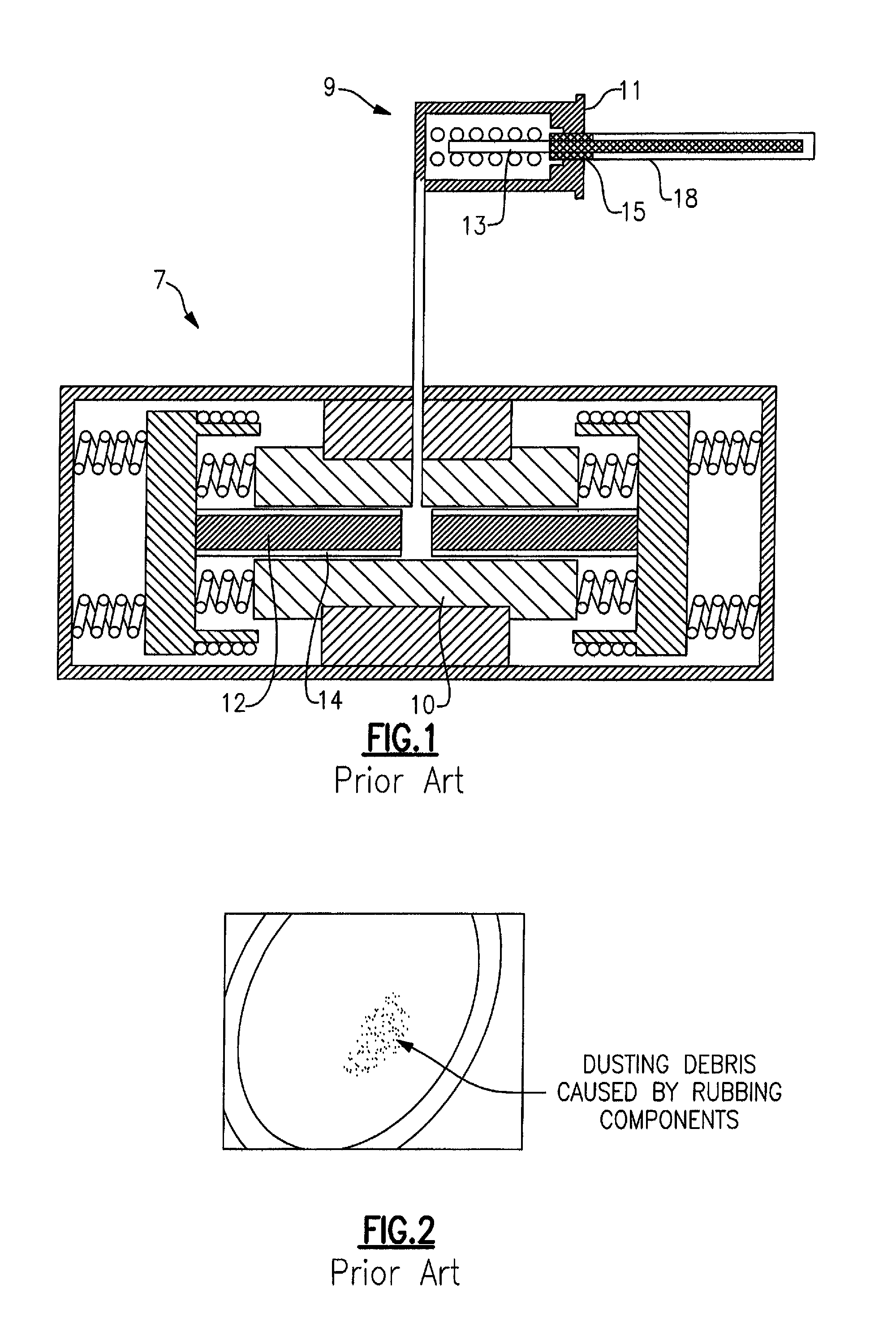
BACKGROUND OF THE INVENTION[0001]The present invention relates to closed cycle cryogenic coolers. More particularly, the present invention relates to an improved piston and spring assembly for use in such cryogenic coolers.[0002]Closed cycle cryogenic coolers (hereinafter “CCCCs”) are known, an example of which may be seen in commonly owned U.S. Pat. No. 5,822,994, the entire disclosure of which is incorporated herein by reference. FIG. 1 of the '994 patent is reproduced as FIG. 1 in the instant application and is seen to include expander section 9 having a cylinder 11 and coldfinger assembly 18 within which is located a low friction linear clearance seal liner 15 bonded to a piston 13. The reciprocating movement of piston 13 is controlled in part by a spring / retainer assembly to control the axial motion of the expander. The principle cooling in a CCCC is accomplished through expansion of the helium working fluid. The expansion is made possible by achieving a phase shift between the...

Claims


Application Information

Patent Timeline
Patent Type & Authority Patents(United States)
IPC IPC(8): F25B9/00F01B29/10
CPCF16F1/125F25B9/14
Inventor DICKEN, LANE DANIELNELSON, ARTHUR R.LUND, JR., DENNIS EUGENEBELK, DANIEL JAMES
Owner COBHAM MISSION SYST DAVENPORT LSS INC
Learn More