Pliers for pressing work pieces

a technology for pliers and work pieces, applied in the direction of pliers, basic electric elements, electric devices, etc., can solve the problems of fixed dependency, user is only capable of applying limited force, and cannot move with fully opened hand levers, so as to achieve the effect of greater pressing for

Active Publication Date: 2012-03-06
WEZAG - WERKZEUGFAB
View PDF25 Cites 11 Cited by
  • Summary
  • Abstract
  • Description
  • Claims
  • Application Information

AI Technical Summary

Benefits of technology

[0037]The use of different transfer mechanisms may especially be suitable for the following purposes and for attaining the following advantages, respectively:
[0040]Due to the choice of the transfer mechanisms and the transmission ratios resulting therefrom, it is possible to allow for especially sensitive setting of the pressing force at the pressing jaws during a partial stroke. This may result in an improved final condition of the pressed work piece.
[0042]It is possible for the user to differentiate less critical parts from more critical parts of the working stroke due to the two partial strokes.
[0050]The concept of the invention may also be roughly summarized in pressing the work piece in two partial strokes with two different individually adapted pliers, these two pliers being combined to one novel pressing pliers. In this way, one attains a compact tool as a unit. For this unit, single structural elements may be used in a multifunctional way for using both “pliers”. This may result in minimization of the material expenditure and a reduced total weight. Furthermore, according to the novel design, both “pliers” operate with the same pressing jaws such that for a change from one “pliers” to the other “pliers”, the pliers after a partial stroke do not have to be reopened intricately, they do not have to be removed from the work piece, the other “pliers” do not have to be brought in their maximum open position, and they do not have to be brought in contact with the work piece for the second partial stroke. During the above described change, there could also be a variation of the position between the work piece and the corresponding parts of the pressing jaws of the first “pliers” and of the second “pliers”. This is prevented according to the present invention. Instead, the pressing jaws of the novel pliers may remain in contact to the work piece during a change from the first partial stroke to the second partial stroke and during use of the first “pliers” and following use of the second “pliers”.
[0063]Preferably, the above mentioned stops become effective approximately 2° to 10°, especially 3° to 4°, before or after an extended position of the toggle lever drive mechanism. In this way, it may be possible to make use of a great working stroke and thus a great angle region of the toggle lever. On the other hand, an end position in which the toggle lever is fully expanded is prevented. Such a position could be a locking position and / or could result in uncontrolled moving condition with “snapping off” from the extended position in both directions.
[0066]For another embodiment of the present invention, a forced locking mechanism is integrated in the novel pressing pliers. Corresponding to the above mentioned prior art references and the advantages resulting therefrom, the forced locking mechanism serves to secure the defined intermediate position of the pressing jaws at one side during the working stroke and during at least one partial stroke, respectively.

Problems solved by technology

One drawback of the above described prior art pressing pliers is that there is a fixed dependency between the opening angle of the pressing jaws, on the one hand, and of the hand levers, on the other hand.
This may be disadvantageous, for example, when the pressing pliers with the die halves have to be moved over a work piece when there only is little space.
In some cases, this movement with the fully opened hand levers is not possible.
Furthermore, when using the known pressing pliers, it has been found that the user is only capable of applying limited forces when the hand levers are wide open, whereas increased actuation forces can be supplied when the hand levers are further closed and can be grasped by one hand or with both hands.
However, no pressing forces or only low pressing forces can be attained for this gear up ratio.
The components forming the toggle lever drive remain unchanged for the above described switching step, whereby there only exist limited possibilities of attaining different gear ratios.
Furthermore, relevant pressing forces can only be produced after the above described gliding movement of the joint pin from one end portion of the elongated hole into the other end portion of the elongated hole.

Method used


Image

  • Pliers for pressing work pieces
  • Pliers for pressing work pieces
  • Pliers for pressing work pieces

Examples


Embodiment Construction

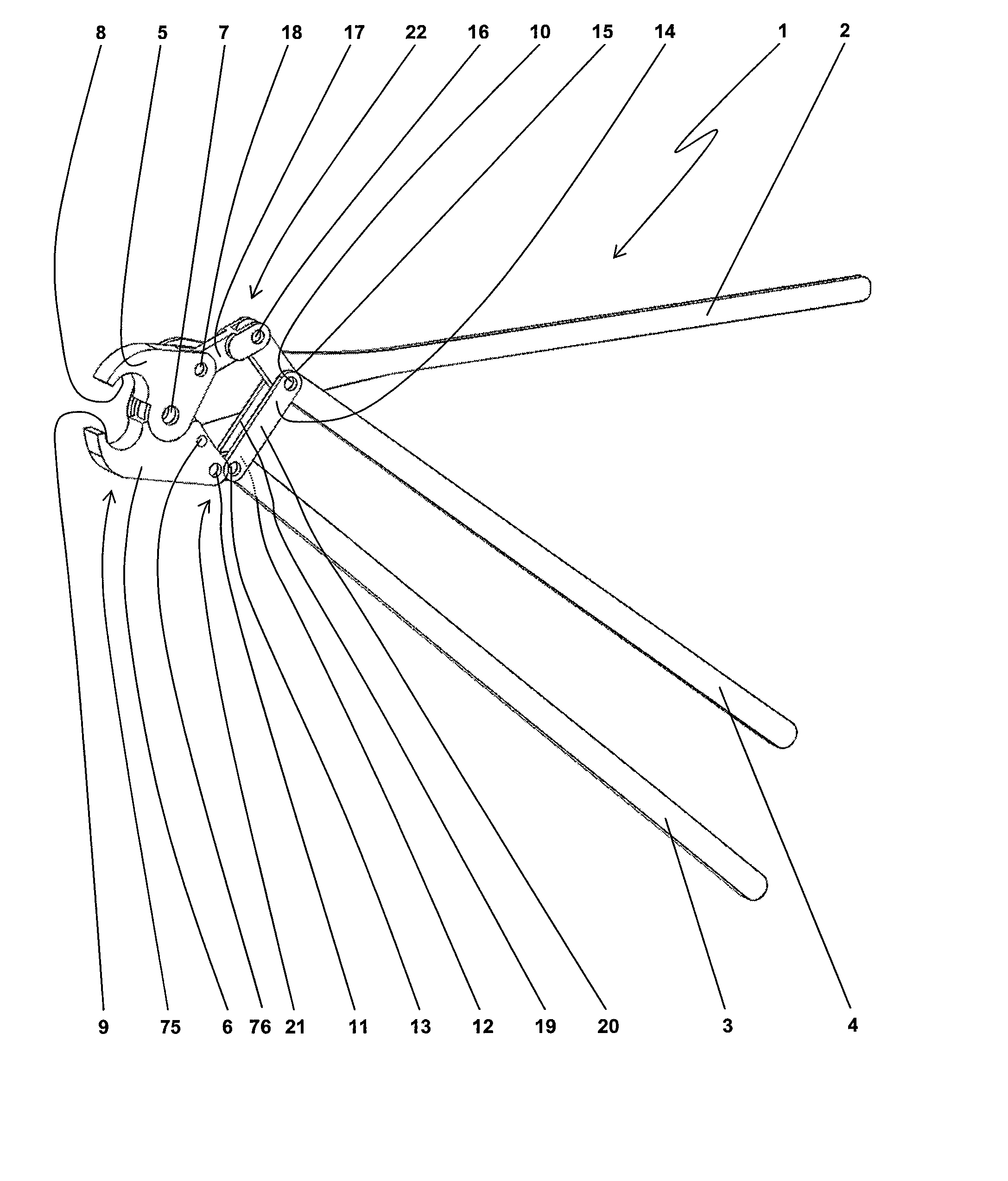
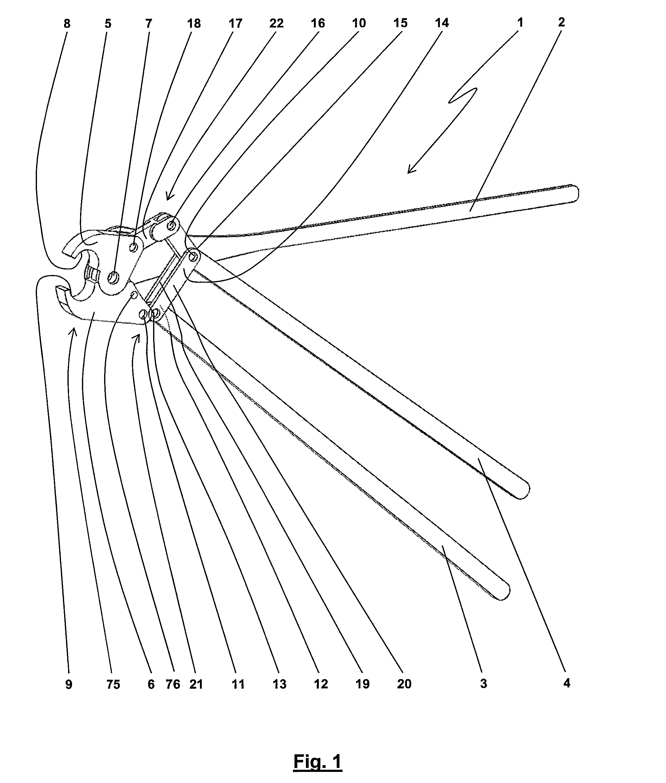
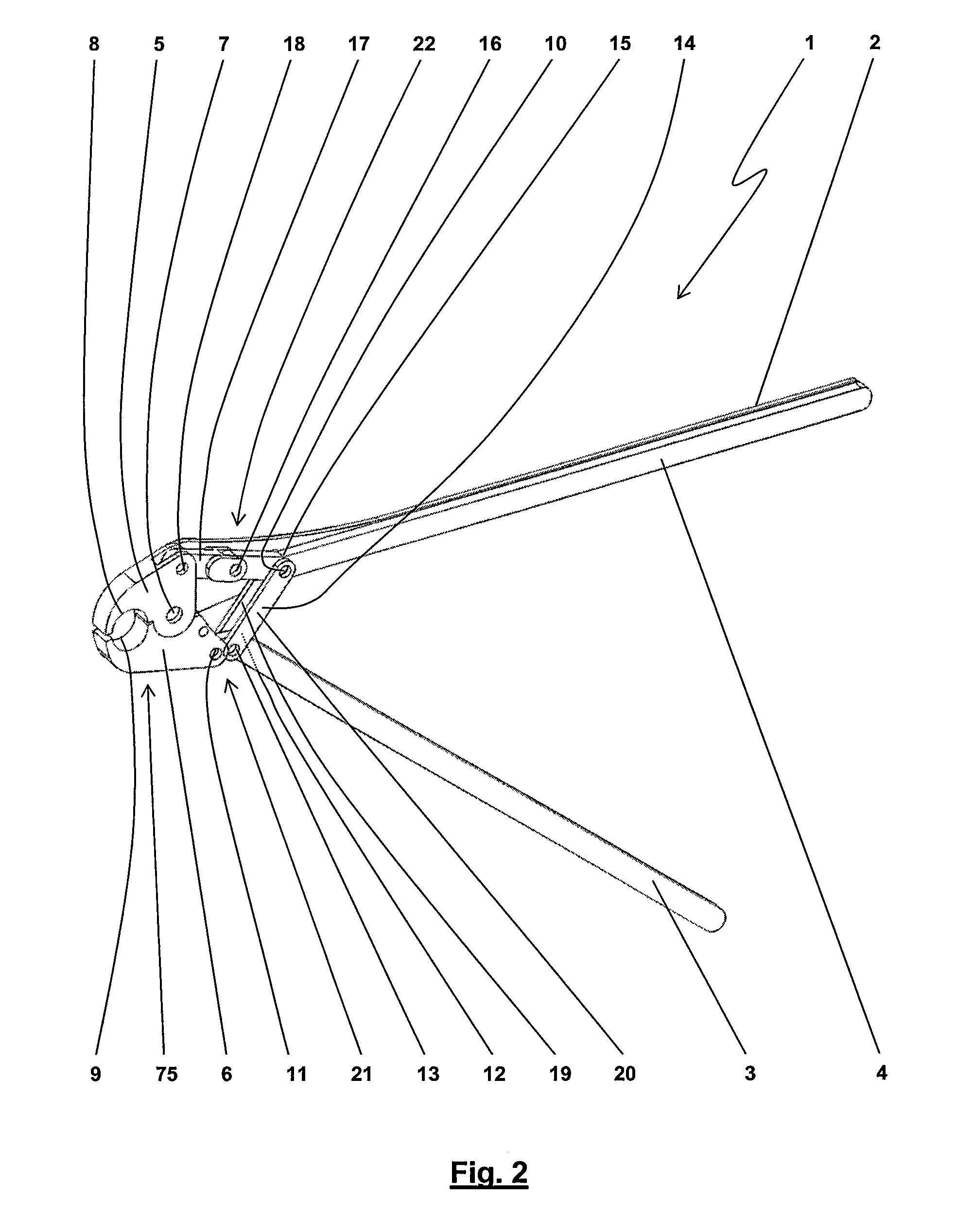
[0090]Referring now in greater detail to the drawings, the figures illustrate exemplary embodiments of novel pressing pliers 1. For example, the pressing pliers 1 serve to deform mountings, tubes, electric contacts, cable lugs, fittings and other similar work pieces by pressing. Pressing is realized by manual actuation, meaning by a human user applying forces, without requiring electric, pneumatic or hydraulic power support. Preferably, the pressing pliers 1 have a structural length which is less than 800 mm, especially less than 700 mm or 600 mm. It is possible to attain pressing forces with the pressing pliers 1 being greater than 40,000 N, especially 50,000 N or 60,000 N by hand forces of a user which are less than 400 N. When using the pressing pliers 1 for pressing and deforming, respectively, a fitting, the fitting may have a diameter of more than 20 mm, especially more than 25 mm, 28 mm or 32 mm.

[0091]FIGS. 1 to 5 illustrate the pressing pliers 1 including three hand levers 2...


PUM


Abstract

Pliers for pressing work pieces such as mountings, electric contacts, cable lugs and fittings include a first hand lever and a second hand lever. The hand levers are movable with respect to one another. The pliers also include a head and at least two pressing jaws being located in the region of the pliers head and approaching one another during a working stroke of the pressing pliers to press a work piece. The working stroke includes a first partial stroke and a second partial stroke. The pliers also include a first transfer mechanism and second transfer mechanism.

Description

CROSS REFERENCE TO RELATED APPLICATIONS[0001]This application claims priority to co-pending German Patent Application No. DE 10 2007 001 235.9 entitled “Presszange zum Verpressen von Werkstücken”, filed Jan. 8, 2007.FIELD OF THE INVENTION[0002]The present invention generally relates to pliers or pressing work pieces. More particularly, the present invention relates to pliers for deforming mountings, electric contacts, cable lugs, fittings and the like by pressing.BACKGROUND OF THE INVENTION[0003]Pressing pliers may serve for realizing general pressing purposes or for electric purposes. In the later case, they are also designated as crimping pliers. Depending on the design of the work piece to be pressed and crimped, respectively, substantial pressing forces have to be applied to attain a desired plastic deformation of a work piece, the work piece being introduced between pressing die halves or die halves of the pressing pliers. The amount of the required pressing force may depend on...

Claims


Application Information

Patent Timeline
Patent Type & Authority Patents(United States)
IPC IPC(8): B25B7/12B25B7/00
CPCB25B27/10B25B27/14H01R43/042
Inventor BATTENFELD, KURT
Owner WEZAG - WERKZEUGFAB
Why Eureka
Try Eureka