
Omnidirectional vertical-axis wind turbine

a vertical-axis, wind turbine technology, applied in the direction of renewable energy generation, machines/engines, climate sustainability, etc., can solve the problems of reducing the overall efficiency of the system, requiring significant power to align such a rotating mass, and uni-directional conventional windmills, so as to achieve the effect of maximizing the extraction of wind energy

Inactive Publication Date: 2012-03-06
PEZARIS CONSTANTINE D
View PDF22 Cites 24 Cited by
  • Summary
  • Abstract
  • Description
  • Claims
  • Application Information

AI Technical Summary

Benefits of technology

"The invention is an omnidirectional vertical-axis wind turbine that maximizes the extraction of wind energy for conversion to mechanical energy. It operates over a wide range of wind velocities and is readily installed with minimal expense and site development. The turbine has two chambers with a vertical shaft and a horn structure that redirects wind from different directions. The redirected wind is then converted into two components of mechanical energy that rotate the shaft, resulting in an increase in the total mechanical energy for rotating the shaft."

Problems solved by technology

However, conventional windmills are unidirectional.
Aligning such a rotating mass requires significant power.
The power required to rotate or position the rotating windmills decreases the overall efficiency of the system.
In some situations where the wind direction fluctuates rapidly, such aligning means may be unable to react in a timely fashion.
Therefore, the efficiency is further reduced.
The primary disadvantage of horizontal axis wind turbine is that it is not omnidirectional.
This creates a large pressure differential between the leading and trailing faces of the rotor blade during the power cycle.
Each of these designs has specific deficiencies.
A number, including conventional windmills, are inefficient in converting the wind's energy into energy that rotates a shaft connected to an electric power generator or other utilization device.
Each is a single-stage structure that can not convert all the energy, so considerable unconverted energy remains in the exhaust.

Method used


Image

  • Omnidirectional vertical-axis wind turbine
  • Omnidirectional vertical-axis wind turbine
  • Omnidirectional vertical-axis wind turbine

Examples


Embodiment Construction

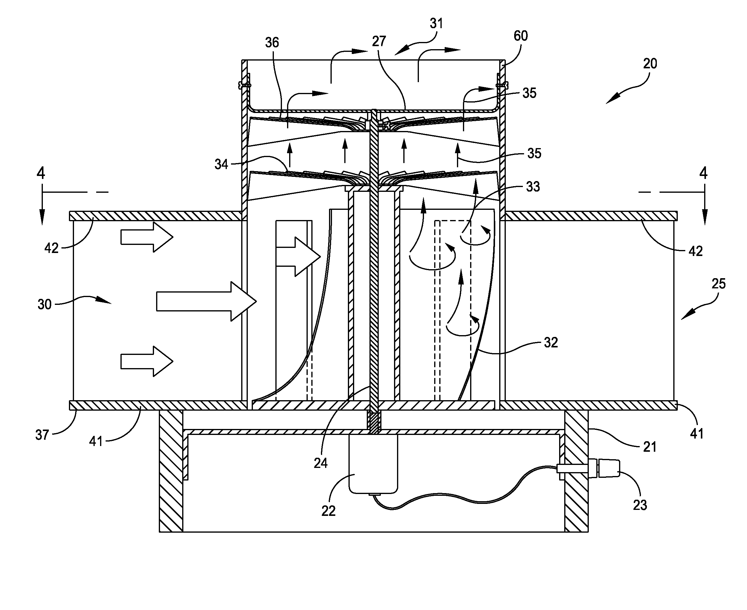
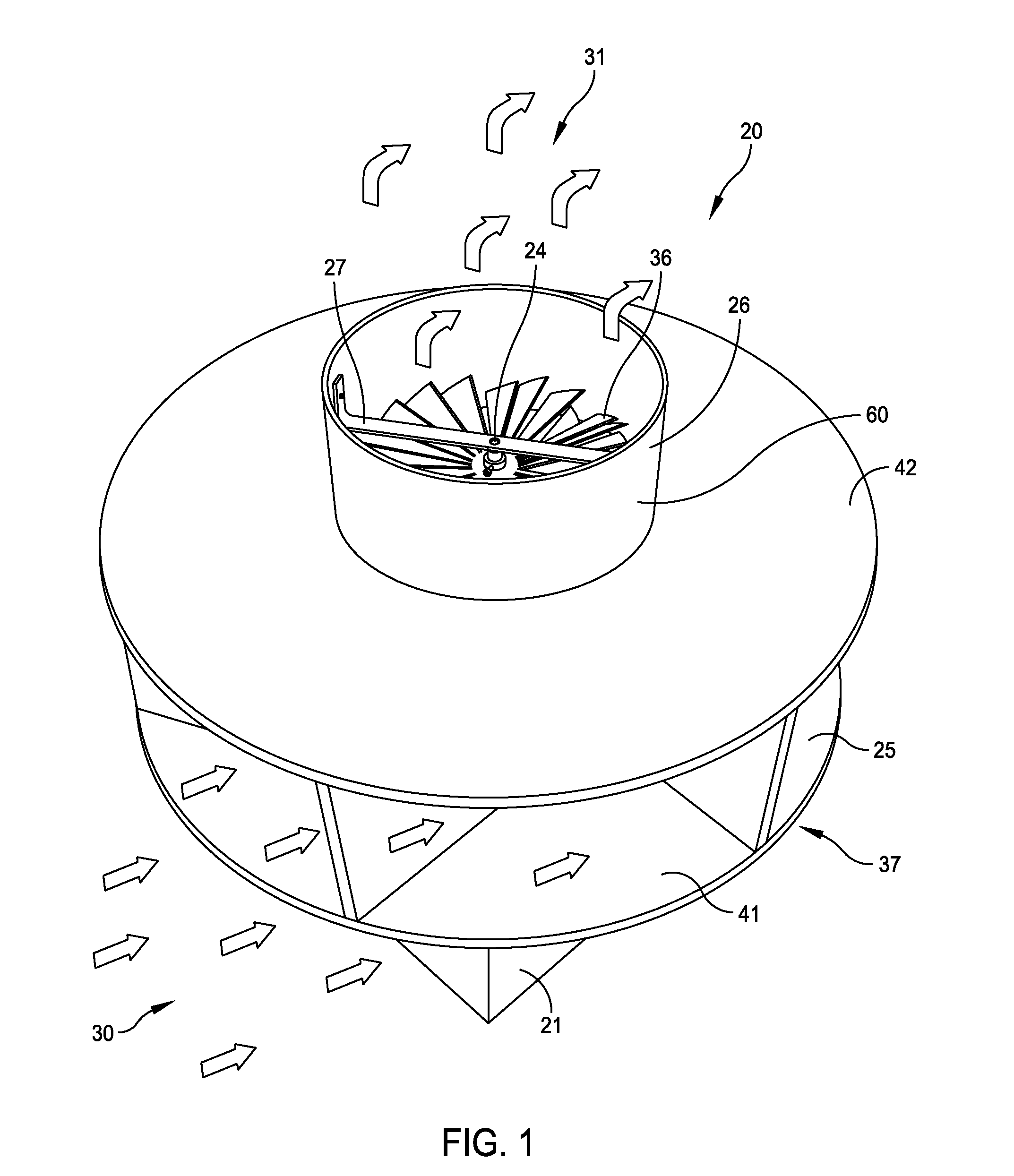
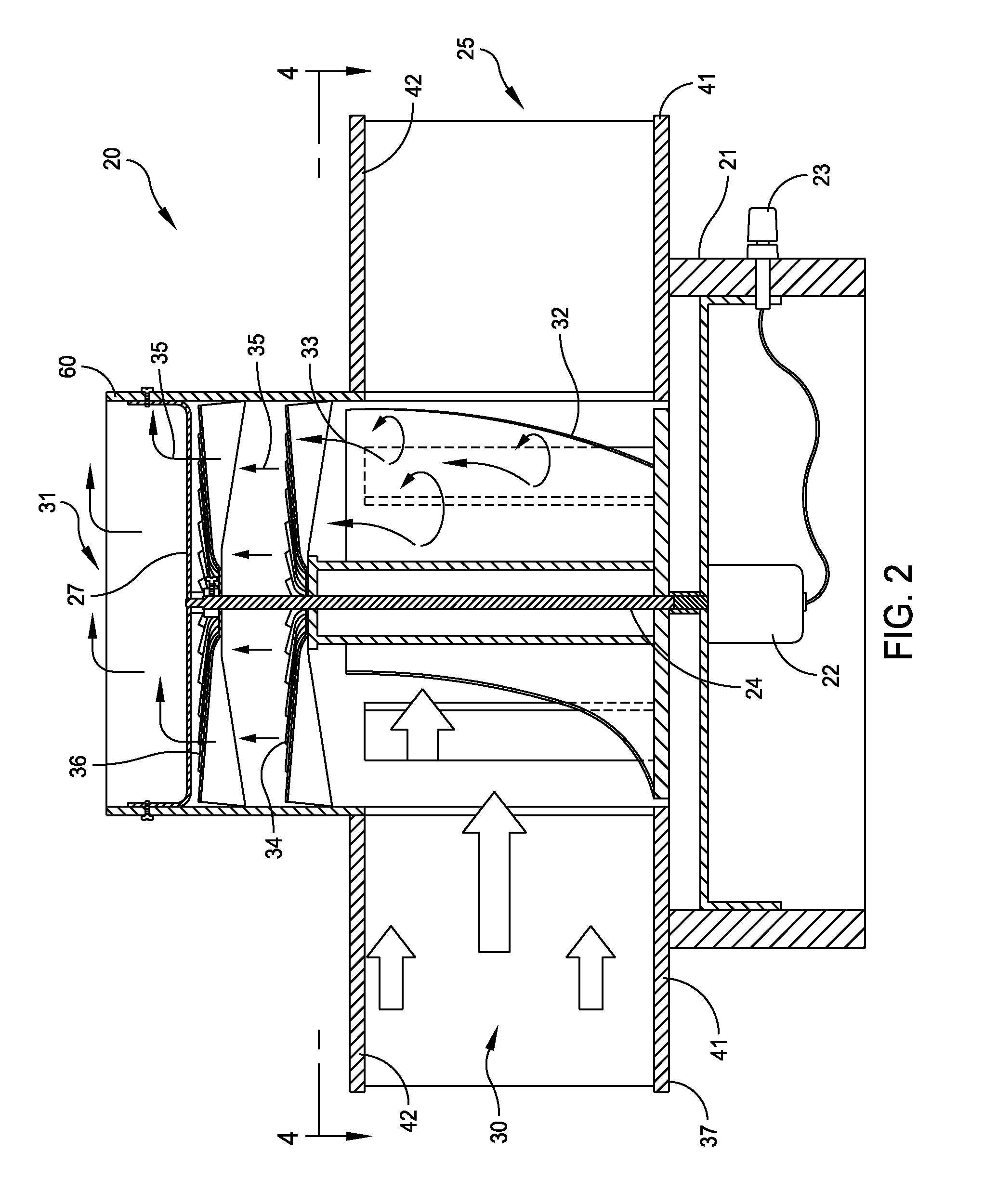
[0026]FIGS. 1 and 2 are perspective and cross-sectional views of one embodiment 20 of a two-stage omnidirectional vertical-axis wind turbine embodying this invention. A base 21 supports the wind turbine on some supporting foundation (not shown). In this embodiment the base 21 also supports a variable speed, constant frequency electric power generator 22 connected to external power connection 23. Specific examples of such variable speed, constant frequency power generation equipment and any other mechanical utilization devices are well known in the art and will be selected based upon well-known design parameters.

[0027]The base 21 supports a first, or lower, chamber 25 and a second, or upper, chamber 26. A vertical shaft 24 extends from the electric power generator 22 through the first chamber 25 into the second chamber 26 to be supported by an end structure represented as a transverse bracket 27 attached to the walls of the second chamber 26.

[0028]In broad terms, as inlet wind 30 ent...


PUM


Abstract

A two-stage, omnidirectional vertical axis wind turbine includes a first chamber in which a plurality of angularly spaced horns guide wind from any side of the wind turbine into a chamber to rotate a first rotor. Wind exiting the first rotor passes through a diverter to produce laminar flow. A fan attached to the shaft intercepts this laminar flow to add additional torque to the shaft.

Description

BACKGROUND OF THE INVENTION[0001]1. Field of the Invention[0002]This invention generally relates to wind-driven power generators. More specifically, this invention relates to omnidirectional vertical-axis wind turbines adapted for driving a variable speed, constant frequency electric power generators and other utilization devices.[0003]2. Description of Related Art[0004]There is increasing interest in developing apparatus for converting wind energy into electric power. Diverse implementations of various concepts have included conventional windmills. However, conventional windmills are unidirectional. That is, they are most efficient only when the axis of rotation of the windmill aligns with the wind direction. Therefore to be efficient a windmill must include some means for aligning the windmill's blades by rotating the axis of rotation about a vertical axis.[0005]Aligning such a rotating mass requires significant power. As wind direction constantly fluctuates, correction must be ap...

Claims


Application Information

Patent Timeline
Patent Type & Authority Patents(United States)
IPC IPC(8): F03D3/04
CPCF03D3/02F03D3/0409F05B2250/323Y02E10/74F03D9/25
Inventor PEZARIS, CONSTANTINE D
Owner PEZARIS CONSTANTINE D
Learn More