
Chest drainage and apparatus for the insertion thereof

a technology for chests and insertion devices, which is applied in the field of chest drainage and apparatus for insertion thereof, can solve the problems of difficult maintenance of sterility in the area of chest tube penetration into the chest, become dangerous instruments, and difficult to perform aseptically in the field of incisions,

Active Publication Date: 2012-03-06
TECHNION RES & DEV FOUND LTD
View PDF10 Cites 14 Cited by
  • Summary
  • Abstract
  • Description
  • Claims
  • Application Information

AI Technical Summary

Benefits of technology

The present invention provides an apparatus for the introduction of a drainage tube into a patient's chest cavity. The apparatus includes a housing with a distal end, a scalpel mechanism, and a trocar. The scalpel mechanism is a sharp instrument that can make incisions in the dermis of the patient. The trocar is a sharp instrument used to puncture the body cavity and create a passage for the drainage tube. The apparatus can be used to secure the drainage tube in place and can be easily removed. The drainage tube has a proximal end and a distal end and may be fitted with an inflatable balloon portion to secure it within the chest cavity. The apparatus can be used in a device for chest drainage. The method of insertion involves providing the apparatus and pressing the distal end of the housing against the patient's chest until the drainage tube is within the chest cavity. The apparatus can be easily removed and the drainage tube can be secured in place.

Problems solved by technology

Such a trocar is useful for initial insertion of the chest tube, but becomes a dangerous instrument once the chest tube is advanced below the level of the ribs.
These incisions are, understandably, difficult to perform aseptically in the field, where the insertion site may be bloody, dirty, or otherwise contaminated.
In addition, maintenance of sterility in the area of chest tube penetration into the chest has been difficult as has been the ability to hold the chest tube in position once it has been introduced into the patient.
The use of surgical gloves to maintain sterility becomes problematic since the gloves become contaminated quickly in the typical field environment.

Method used


Image

  • Chest drainage and apparatus for the insertion thereof
  • Chest drainage and apparatus for the insertion thereof
  • Chest drainage and apparatus for the insertion thereof

Examples


Embodiment Construction

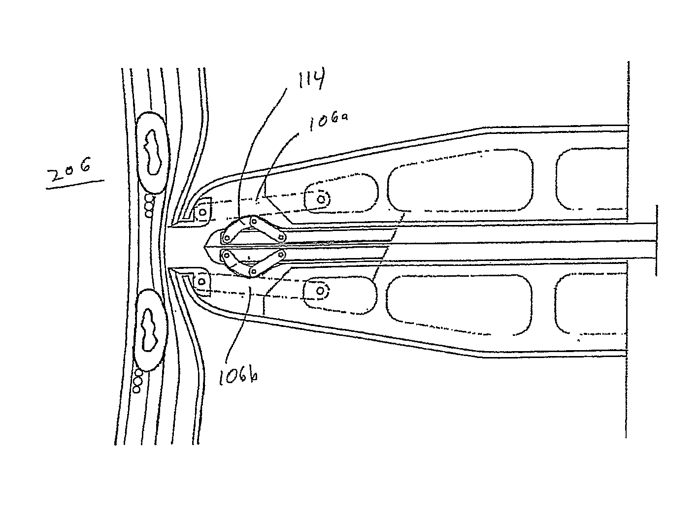
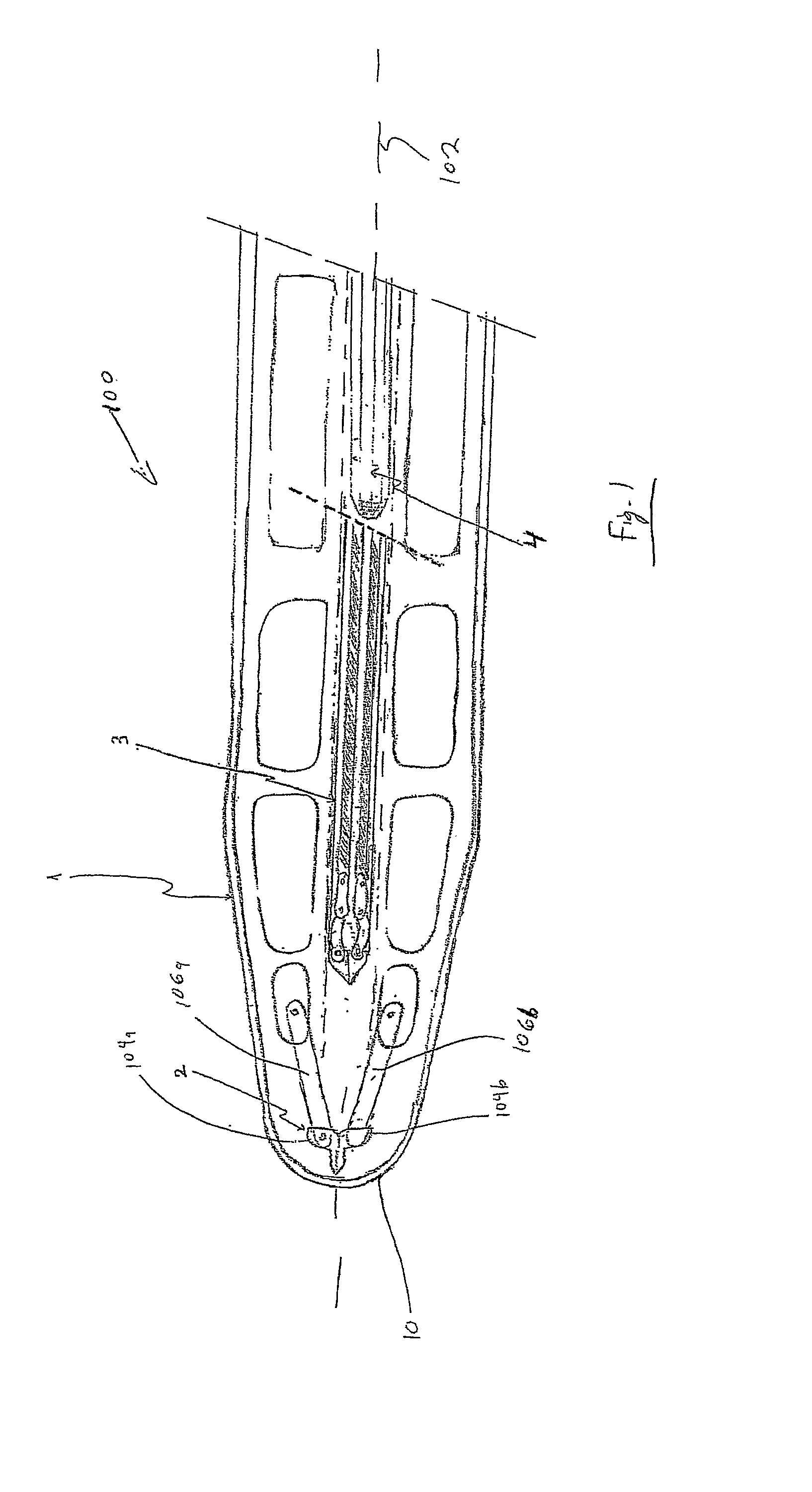
[0053]As illustrated in FIG. 1, there is provided an apparatus, which is generally indicated at 100, for the introduction of a drainage tube into a patient's chest cavity. The apparatus 100 comprises a housing 1, a scalpel mechanism 2, a trocar 3, and a drainage tube 4. The elements of the apparatus 100 are arranged such that initially, the scalpel mechanism 2 is located distally of the trocar 3, and the trocar is located distally of the drainage tube 4.

[0054]The housing 1 is formed as an elongate pipe made of hard material, such as injected plastic, and has a longitudinal axis 102 along the center thereof. A distal end 10 of the housing is rounded in three-dimensions.

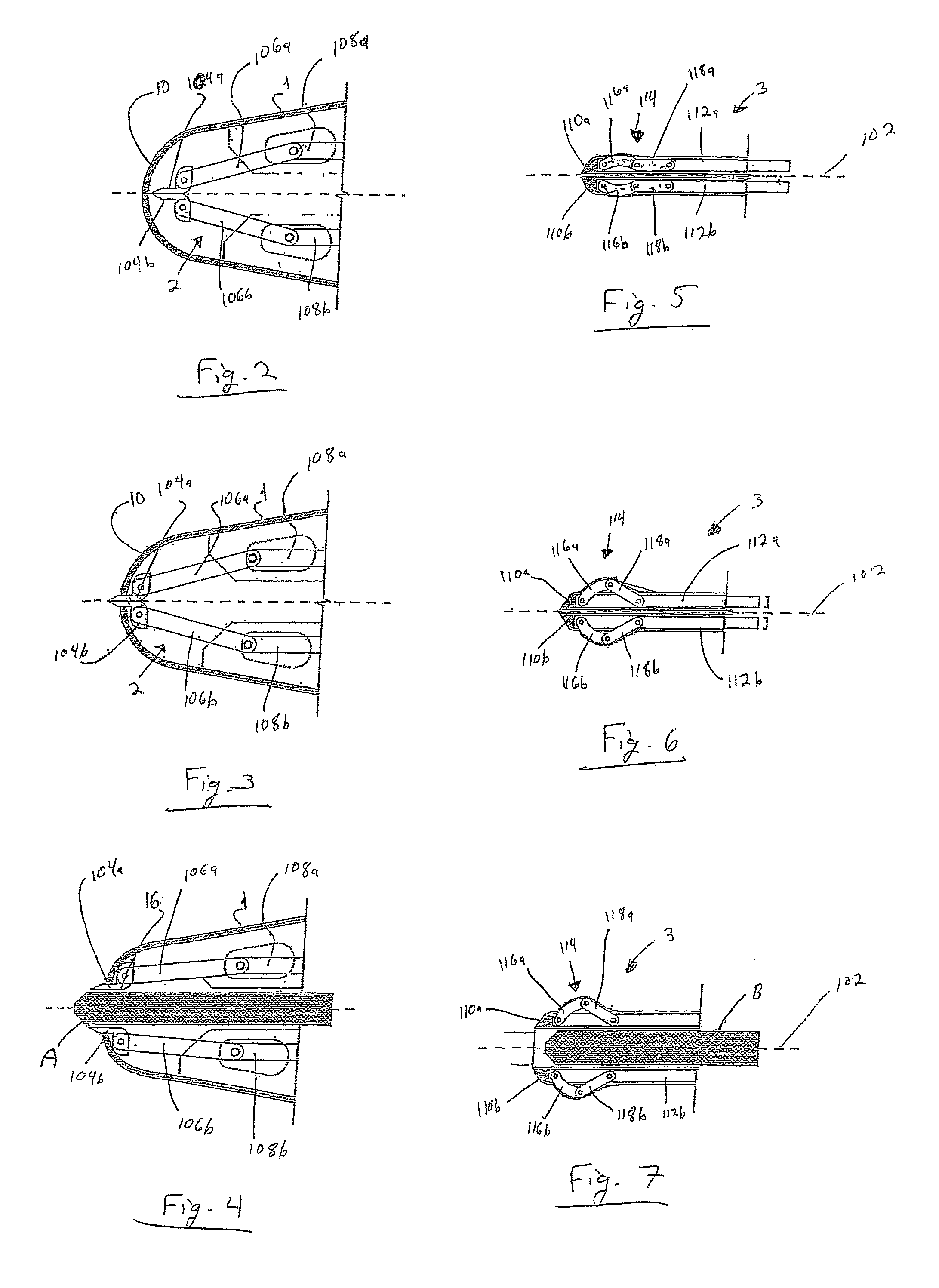
[0055]As best seen in FIGS. 2 through 4, the scalpel mechanism 2 comprises two cutting portions 104a, 104b, which are arranged opposite one another. FIG. 1 illustrates scalpel mechanism 2 in its closed position, wherein the cutting portions 104a, 104b are adjacent one another. The scalpel mechanism further comprises sc...


PUM


Abstract

An apparatus for the introduction of a drainage tube into a patient's chest cavity, comprising a housing having a distal end, a proximal end, and a longitudinal axis; a scalpel operable in a protruding position between a closed position in which the cutting portions are adjacent one another and adapted to make an incision in the dermis of the patient, and an open position in which the cutting portions are spaced from one another forming a scalpel passage along the longitudinal axis between the cutting portions. The apparatus further comprising a trocar comprising first and second trocar portions, each extending along the length of the trocar; the trocar being operable between an closed position wherein the first and second trocar portions are substantially adjacent one another, and a closed position in which the first and second trocar portions are spaced from one another and adapted for the introduction of the drainage tube therethrough.

Description

[0001]This is a National Phase Application filed under 35 U.S.C. 371 as a national stage of PCT / IB2008 / 000898, filed Apr. 14, 2008, an application claiming the benefit under 35 U.S.C. 119(e) U.S. Provisional Application No. 60 / 907,696, filed Apr. 13, 2007, the content of each of which is hereby incorporated by reference in its entirety.FIELD OF THE INVENTION[0002]This invention relates to devices for the drainage of fluid from a patient's body, and, particularly, for the drainage of air from pleural space in a patient's chest cavity. In addition, it relates to apparatuses adapted to insert such devices into the chest cavity.BACKGROUND OF THE INVENTION[0003]Chest drainage tubes for the drainage of air trapped in a patient's thorax or pleural space (hereafter referred to collectively as a “chest cavity”) are often used to allow for drainage of air trapped therein following trauma. Typically, such chest tubes have one or more holes at a distal end, and a lumen in fluid communication th...

Claims


Application Information

Patent Timeline
Patent Type & Authority Patents(United States)
IPC IPC(8): A61B17/34A61F2/958
CPCA61B17/3211A61B17/3415A61B17/3439A61B17/32093
Inventor HASSIDOV, NOAMSOMER-LAPID, MERAV
Owner TECHNION RES & DEV FOUND LTD
Learn More