Methods for high speed reading operation of phase change memory and device employing same

a phase change memory and reading operation technology, applied in the field of memory devices, can solve the problem of limiting the speed at which the phase change memory can be read, and achieve the effect of extending the usefulness of the device, high speed operation, and slowing down the behavior of the set speed

Active Publication Date: 2012-03-13
MACRONIX INT CO LTD
View PDF388 Cites 2 Cited by
  • Summary
  • Abstract
  • Description
  • Claims
  • Application Information

AI Technical Summary

Benefits of technology

[0015]As a result, the recovery time of the phase change material limits the speed at which the phase change memory can be read following a set or reset operation.
[0017]Thus, high speed read after program operations are demonstrated in which the sum of the pulse width of the programming and a time interval between the programming pulse and a read pulse is less than or equal to 70 ns. In some embodiments the sum is less than or equal to 50 ns, being less than or equal to 15 ns in certain embodiments. As a result, the phase change memory element can be operated at high speeds, such as those typically required of DRAM and SRAM.
[0021]Additionally, the operations described herein comprising set and reset pulses having opposite voltage polarity are shown to result in a fast transition to the lower resistance state. Thus, the operations herein overcome the slow set speed behavior of memory cell structures such as small bridge-type memory cells which suffer significant thermo-electric effects that cause asymmetrical heating in the body of the phase change material.
[0022]As a result, phase change based memory devices and methods for operating described herein overcome the performance limitations of slow set speeds and long recovery times commonly associated with phase change memory devices, enabling high speed operation and extending their usefulness into applications typically filled by DRAM and SRAM memory.

Problems solved by technology

As a result, the recovery time of the phase change material limits the speed at which the phase change memory can be read following a set or reset operation.

Method used


Image

  • Methods for high speed reading operation of phase change memory and device employing same
  • Methods for high speed reading operation of phase change memory and device employing same
  • Methods for high speed reading operation of phase change memory and device employing same

Examples


Embodiment Construction

[0042]The following description of the disclosure will typically be with reference to specific structural embodiments and methods. It is to be understood that there is no intention to limit the disclosure to the specifically disclosed embodiments and methods, but that the disclosure may be practiced using other features, elements, methods and embodiments. Preferred embodiments are described to illustrate the present disclosure, not to limit its scope, which is defined by the claims. Those of ordinary skill in the art will recognize a variety of equivalent variations on the description that follows. Like elements in various embodiments are commonly referred to with like reference numerals.

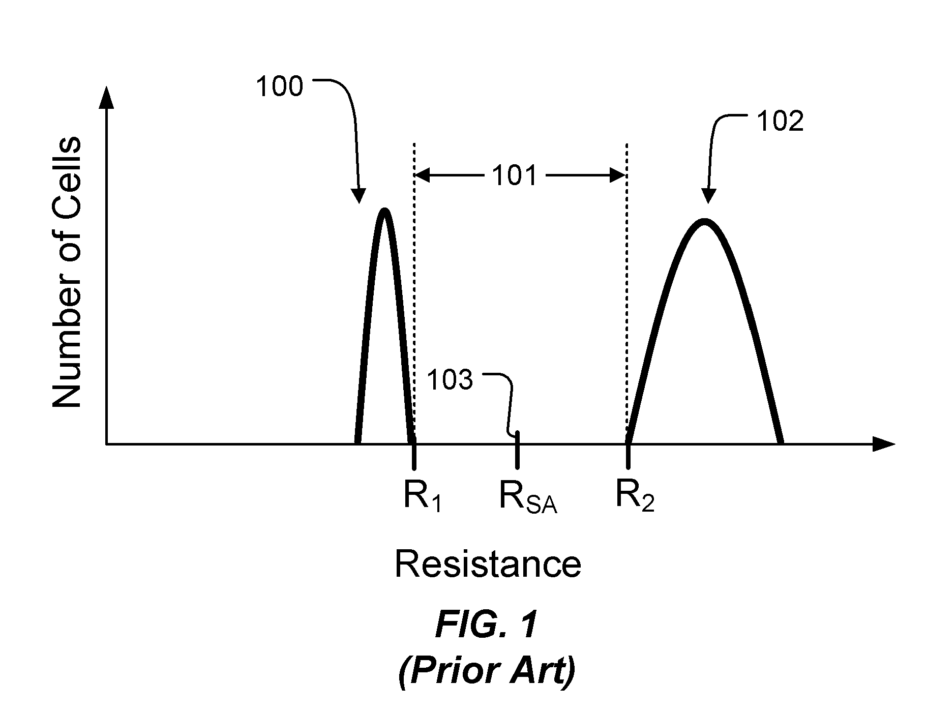
[0043]In phase change memory, data is stored by causing transitions in an active region of the phase change material between amorphous and crystalline phases. FIG. 1 is an example distribution of the resistance for a number of memory cells each comprising a phase change memory element. The phase cha...


PUM


Abstract

Phase change based memory devices and methods for operating described herein overcome the performance limitations of slow set speeds and long recovery times commonly associated with phase change memory devices, enabling high speed operation and extending their usefulness into high speed applications typically filled by DRAM and SRAM memory.

Description

CROSS-REFERENCE TO RELATED APPLICATIONS[0001]This application claims the benefit of U.S. Provisional Application No. 61 / 076,516 titled “A Method for High Speed Reading Operation of Phase Change Memory and Device Employing Same” filed Jun. 27, 2008.[0002]This application is related to U.S. patent application Ser. No. 12 / 432,055 entitled “Bipolar Switching of Phase Change Device”, filed on Apr. 29, 2009.BACKGROUND OF THE INVENTION[0003]1. Field of the Invention[0004]The present invention relates to memory devices based on phase change based memory material, including chalcogenide based materials and other materials, and methods for operating such devices.[0005]2. Description of Related Art[0006]Phase change based memory materials, like chalcogenide based materials and similar materials, can be caused to change phase between an amorphous and a crystalline state by application of electrical current at levels suitable for implementation in integrated circuits. The generally amorphous sta...

Claims


Application Information

Patent Timeline
Patent Type & Authority Patents(United States)
IPC IPC(8): G11C11/00
CPCG11C13/0004G11C13/0069G11C2013/0092G11C2013/0073
Inventor LIN, YUYUCHEN, YI-CHOU
Owner MACRONIX INT CO LTD
Why Eureka
Try Eureka