Telecommunication enclosure monitoring system

a technology for monitoring systems and enclosures, applied in the direction of transmission monitoring, frequency-division multiplexes, instruments, etc., can solve the problem of insufficient mechanical lock to lock the door

Active Publication Date: 2012-03-13
3M INNOVATIVE PROPERTIES CO
View PDF16 Cites 183 Cited by
  • Summary
  • Abstract
  • Description
  • Claims
  • Application Information

AI Technical Summary

Problems solved by technology

It is often desirable to control access to such rooms or cabinets, and in such situations it may prove insufficient to lock the door with a mechanical lock.

Method used


Image

  • Telecommunication enclosure monitoring system
  • Telecommunication enclosure monitoring system
  • Telecommunication enclosure monitoring system

Examples


Embodiment Construction

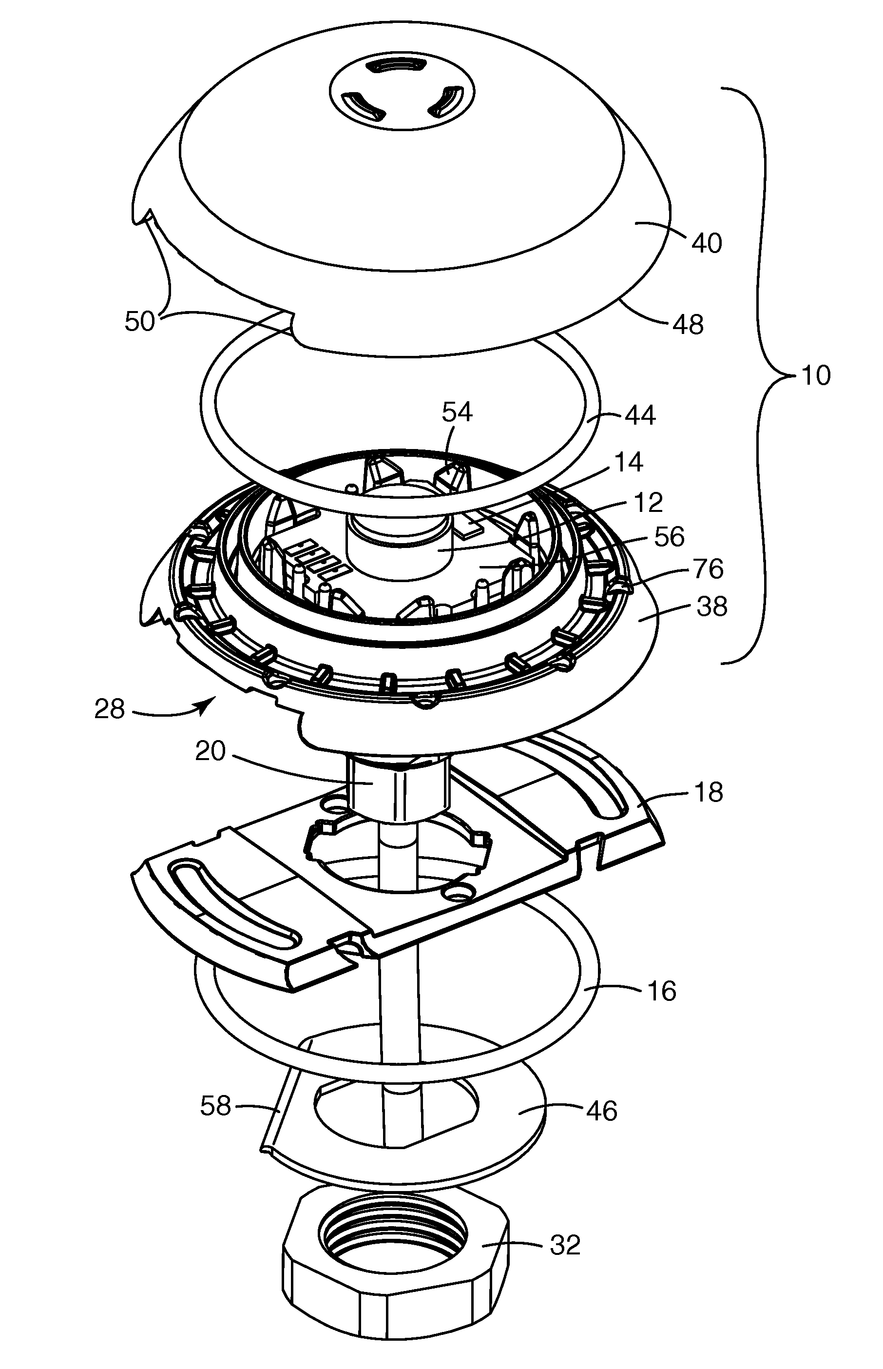
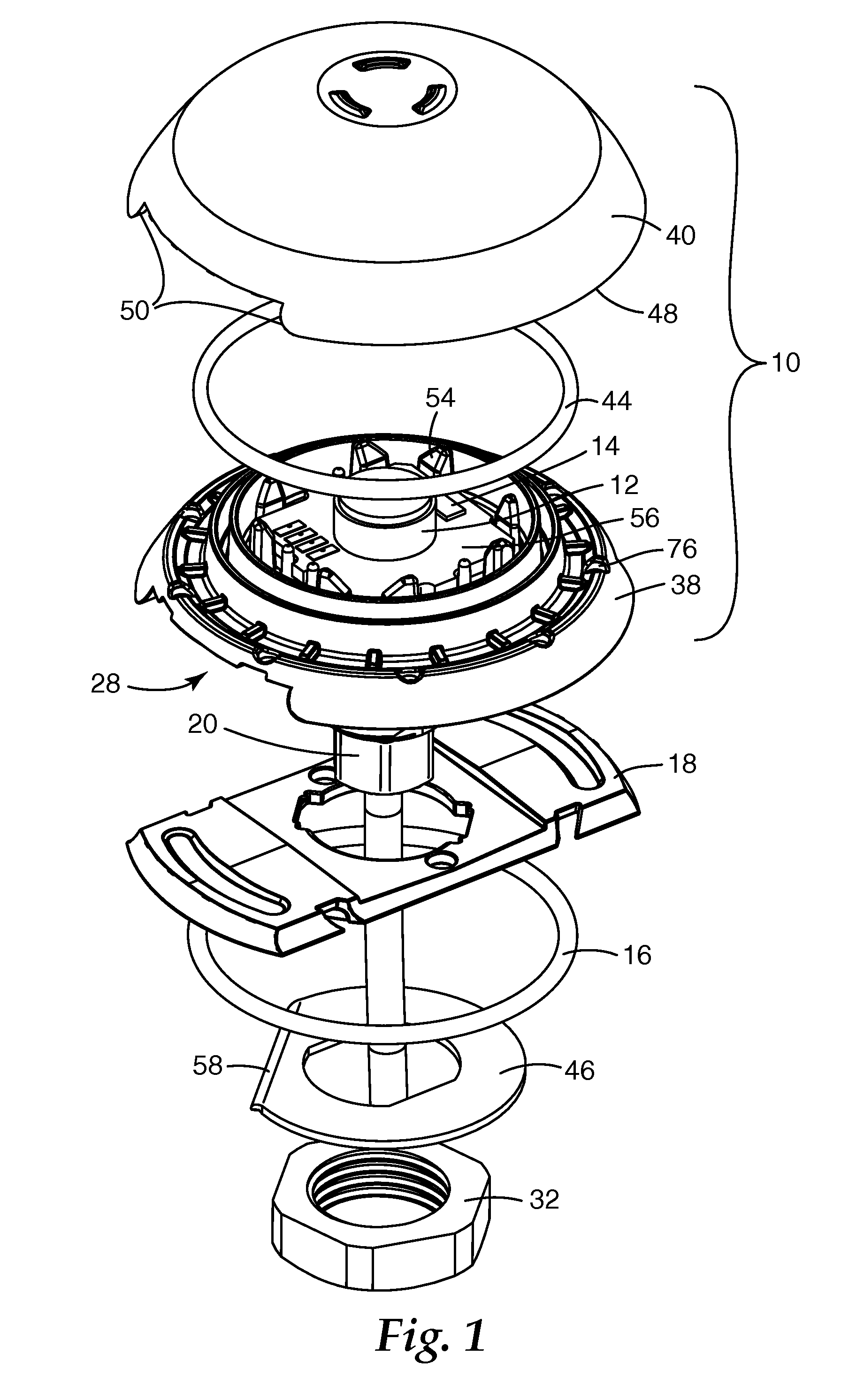
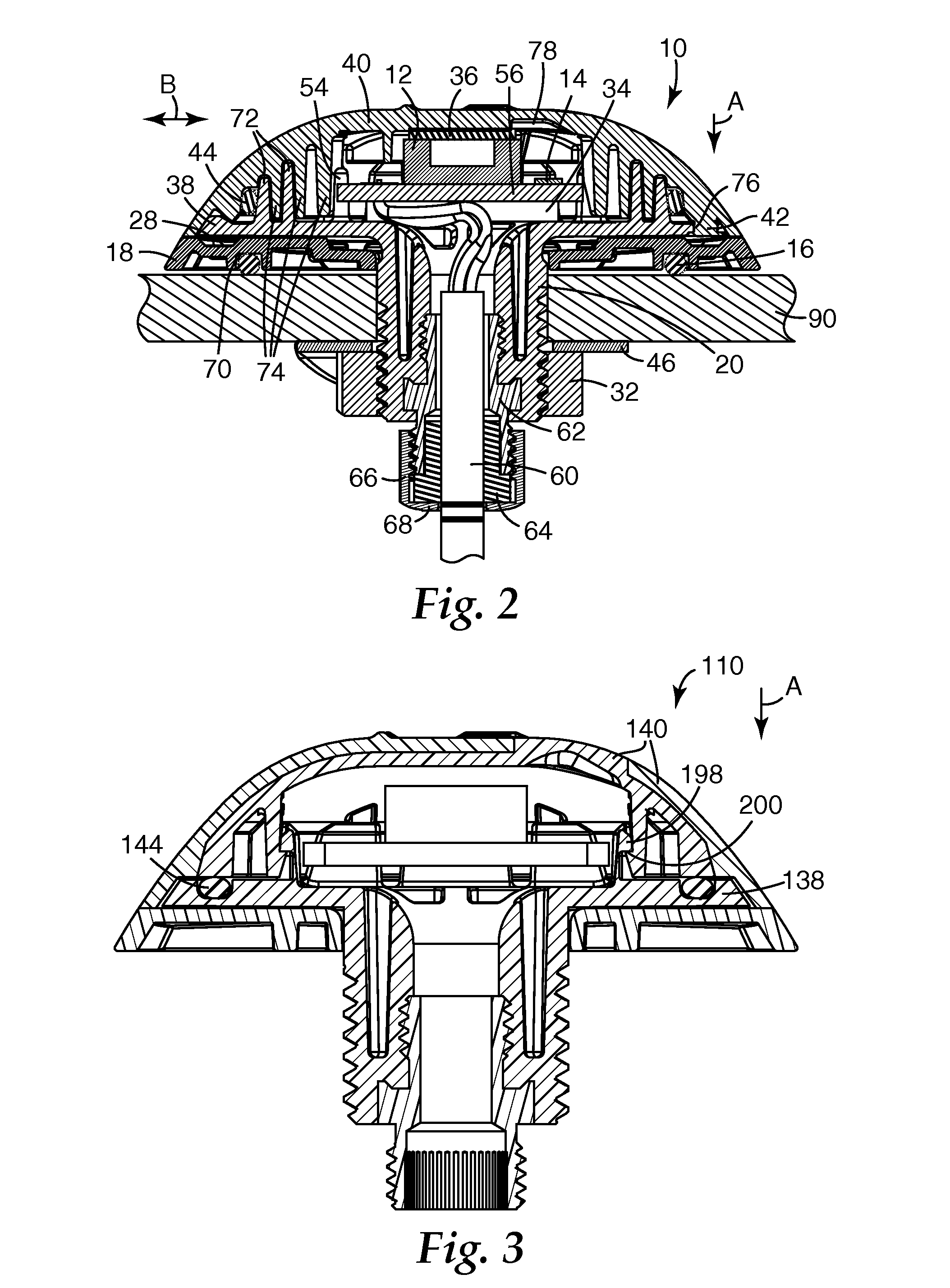
[0022]A remote monitoring system for telecommunication enclosures includes a low profile or flush mounted sealed transceiver or antenna unit and is described herein. FIGS. 1-7 particularly show exemplary embodiments of a transceiver housing unit and its attachment components. FIG. 8 shows an exemplary telecommunication enclosure that can utilize the sealed transceiver unit. FIGS. 9-11 show exemplary monitoring systems. These figures are each described in particularity further below.

[0023]In a preferred aspect, the remote monitoring system described herein can allow a craftsman to perform status checks, gather information, initiate test protocols, download software to electronic equipment or modules within a telecommunication enclosure without the need for a direct hard wire connection or without having to open the enclosure to gain physical access to the interior of the enclosure. A remote communication device can send a signal to a transceiver located on the external surface of the...


PUM


Abstract

A remote monitoring system for telecommunication enclosures includes a low profile or flush mounted sealed transceiver or antenna unit, an electronic module inside of the enclosure electrically connected to the transceiver and a communication device to send signals to the electronic module through the transceiver. The sealed housing generally comprises a portion extending through the exterior surface of the enclosure. In some embodiments, the transceiver may include a radio frequency antenna, a photoelectric cell, a light sensor or an infrared sensor, and the communication device may be a handheld device, a transponder, or a networked computer.

Description

CROSS REFERENCE TO RELATED APPLICATION[0001]This application claims the benefit of U.S. Provisional Application No. 60 / 746,241, filed May 2, 2006, the disclosure of which is incorporated by reference herein in its entirety.BACKGROUND[0002]In various technical fields, a variety of objects or installations are accommodated in rooms or cabinets that may be closed with a door. It is often desirable to control access to such rooms or cabinets, and in such situations it may prove insufficient to lock the door with a mechanical lock. It is possible, for example, for a person not authorized to access the room or cabinet to gain possession of a key to the mechanical lock. For this reason electronic locks are sometimes used, since unauthorized access can be prevented more easily, or at least be monitored to know who and when a protected area is accessed. An electronic lock can, for example, be connected to a centralized security system and there monitored for unauthorized access.[0003]In the ...

Claims


Application Information

Patent Timeline
Patent Type & Authority Patents(United States)
IPC IPC(8): H04B17/00
CPCG07C11/00H04L43/0817H04Q1/149
Inventor LANGSWEIRDT, RONALD L.ANDERS, HERBERTLINDENBECK, BERNDSCHNEIDER, BERNHARDHAHN, JOERGSTAROSTA, MARIANSTEINBRINK, MANUELSTIEGLITZ, MANFRED
Owner 3M INNOVATIVE PROPERTIES CO
Why Eureka
Try Eureka